


Then mark wire
with label shown
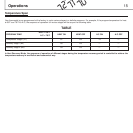
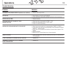
If the code letter on the
existing thermostat is
R, R
H
, R
C
(V), (VR)
Y, Y
1
, (M), (M
1
)
W, W
1
(M)
W
2
(Y
2
)
G (F)
E
A
O, B (SEE NOTE 1)
B, C, (X)
Comments
Hot wire of 24V transformer
Activates when first stage of compressor is called (Heater/Cool)
Activates when first stage of auxiliary heat is called or com-
pressor heat in NR mode
Activates only when second stage of auxiliary heat is called
Always activates when system is on
Always on in emergency mode; off in normal mode
Always on in normal mode; off in emergency mode
RO = Activates in cool mode
RB = Activates in heat mode
NR = Does not activate
Common wire of 24V AC transformer
Function
24V Wire
First stage of compressor
First stage of auxiliary heating
(First stage heat in NR mode)
Second stage of auxiliary heating
(First stage of auxiliary heat in NR mode)
Fan
Emergency heat relay (If available)
Controls outdoor thermostat
Normal compressor operation relay
(If available)
Reversing valve operation
Common wire (If available)
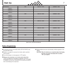
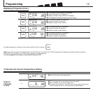
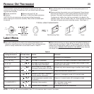
Remove Old Thermostat
This thermostat comes with two #8 slotted screws and two wall
anchors for mounting. To install your unit, you should have the follow-
ing tools and materials.
■ Slotted screwdriver ■ Electric drill and 3/16" bit
■ Hammer ■ Three 1.5 (AA) Size Alkaline batteries
CAUTION: Do not remove any wiring from existing thermostat
before reading the instructions carefully. Wires must be labeled prior
to removal.
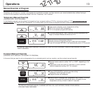
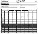
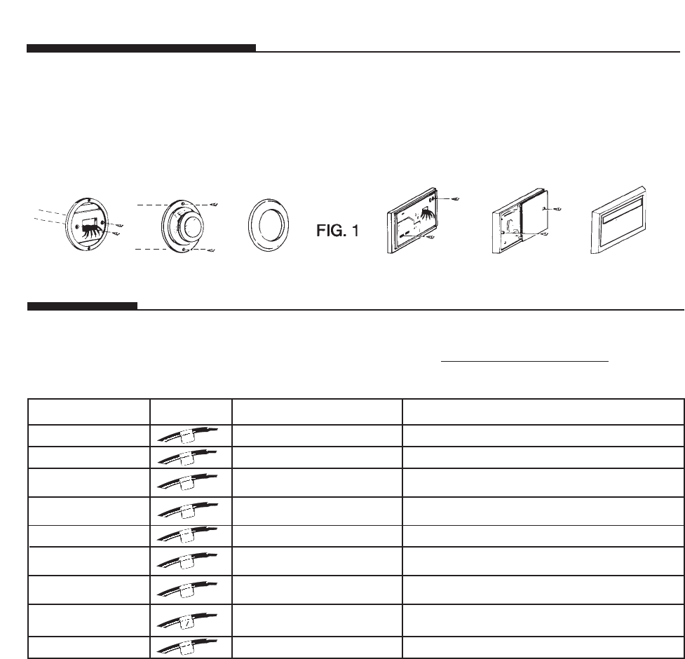
Label Wires
Table A
20
■ Before disconnecting any wires, apply the self-adhesive labels pro-
vided to the wire as shown in Table A. (For example, attach the label
marked W to the wire which goes to the W or H terminal on the exist-
ing thermostat.) IGNORE THE COLOR OF THE WIRES
since these do
not always comply with the standard.
■ Each wire coming from the wall to the existing thermostat is con-
nected to a terminal point on that thermostat. Each of these terminal
points is usually marked with a code letter shown in Table A.
R
Y
1
W
1
W
2
NOTE: 1. If “O” and “B” are both available, then “B” is the common wire in most of the cases.
G
E
A
O
B
C
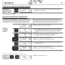
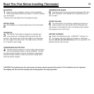
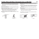
TYPICAL HOME THERMOSTATS
Wall Mounting Plate Thermostat Cover Wall Mounting Plate Thermostat Cover
■ Turn off the power to the furnace at the main power panel or at
the furnace.
■ Remove existing thermostat cover and thermostat. Some thermo-
stats will have screws or other locking devices that must first be
removed. Once wall mounting plate is exposed, look for wires.
If wires are not visible, they may be connected to the back of the
wallplate. Again, look for screws, tabs, etc. Some models have doors
that open to expose wires and mounting screws. (See Figure 1.)