


12
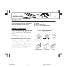
INSTALLATION
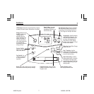
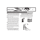
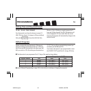
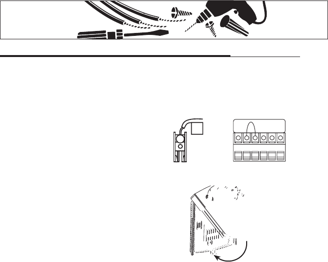
Connect Wires and Mount Thermostat Cover to Wall Plate
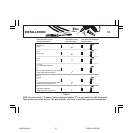
■ Match and connect the labeled wires to the appro-
priate coded terminal screws on the wallplate. (See
Figure 4, 5.) Ignore any wires which may be present,
but which were not connected to the old thermostat.
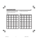
■ Refer to the Wiring Diagrams below to be sure your
system is wired correctly.
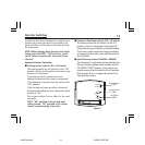
■ If your system is a single-stage heat pump and
uses an O or B wire, you must move the System
Selector switch inside the thermostat to the Heat
Pump position. If you have a normal furnace or
electric system, leave the switch in the Standard
position. Refer to the System Selector section on
the back for more information on this switch.
■ Be sure to tighten the terminal screws securely,
otherwise a loose wire could cause operational
problems with your system or thermostat.
■ Push excess wire back into the hole to prevent interfer-
ence when installing the thermostat to the wallplate.
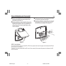
■ Make sure the System Switch is set to OFF, and the
Fan Switch is set to AUTO.
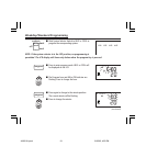
■ Insert the bottom tab on the thermostat body into
the slot at the bottom of the wallplate. Press the
top of the thermostat body to snap it into the
wallplate. Refer to Figure 6. (NOTE:
Do not force
the thermostat onto the wallplate, as the ter-
minal pins may be damaged. If it does not
snap properly, the thermostat may not work.
)
■ Insert the two AA size alkaline batteries, observing
the polarity marked inside the battery compartment.
■ Switch on the main power at the panel or furnace.
x
RH
Figure 4 Figure 5
GRcRhY/O W/B Y1
Figure 6