13
SECTION II – INSTALLATION AND OPERATION
WARNING / CAUTION
DO NOT TURN ON THE STEAM SUPPLY to this unit until heater is completely filled with water
and all air has been released. If the heater is NOT filled with water when the steam supply is turned
on, damage to the heating coil may result.
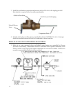
For protection against excessive pressures and temperatures, local codes require the installation of a
temperature-and-pressure (T&P) relief valve certified by a nationally recognized laboratory that
maintains periodic inspection of production of listed equipment of materials, as meeting the
requirements for Relief Valves and Automatic Gas Shutoff for Hot Water Supply Systems. ANSI
Z21.22-1971. THE CUSTOMER IS RESPONSIBLE TO PROTECT PROPERTY AND
PERSONNEL FROM HARM WHEN THE VALVE FUNCTIONS.
All water heaters have a risk of leakage at some unpredictable time. IT IS THE CUSTOMER'S
RESPONSIBILITY TO PROVIDE A CATCH PAN OR OTHER ADEQUATE MEANS, SO THAT
THE RESULTANT FLOW OF WATER WILL NOT DAMAGE PROPERTY.
If unit is painted or insulated on the job site, care should be taken not to paint or insulate over the
A.S.M.E. nameplate. This plate should be accessible and legible at all times to inspectors, and
information from this plate must be used when ordering parts from the factory.
The tank should be fully drained in the event the steam has been turned off and if there is danger of
freezing. If tank is drained and to be left empty for more than 8 hours, at least 2-inches of water should
be left in the bottom of cement lined tanks to prevent lining from drying and cracking.
WATER HEATER PLACEMENT
1. Adequate space should be provided for removal of heating element.
2. Unit should be level to permit proper drainage
PIPING INSTALLATION
NOTE:
The most effective means for preventing deterioration from accelerated corrosion due to
galvanic and stray current is the installation of dielectric fittings/unions. The installation of these
fittings is the responsibility of the installing contractor.
1. All integral components have been properly sized to meet design conditions. Piping to the
unit should be sized to meet the design conditions, as dictated by good engineering practices.
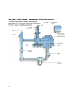
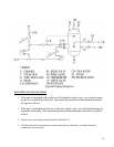
2. Refer to the enclosed drawing for location of piping connection.


