


SECTION 2
Mounting and Wiring the Control
Installing the Control Cabinet and PC Board
Cabinet and Lock
1. Mount the control cabinet to a
sturdy wall in a clean, dry area,
which is not readily accessible to
the general public, using fasteners
or anchors (not supplied) with the
four cabinet mounting holes.
2. Remove cabinet door, then remove
the lock knockout from the door.
Insert the key into the lock.
CABINET DOOR
BOTTOM
LOCKED
UNLOCKED
cab_lock_snap-001-V0
ADEMCO
ADEMCO
PUSH
SNAP
TAB
SNAP
TAB
PUSH
ON LOCK
UNTIL IT
IS SEATED
SECURELY
STEP 2STEP 1
CHECK
POSITION
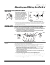
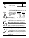
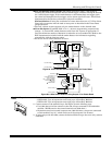
Figure 1. Installing the Cabinet Lock
3. Position the lock in the hole, making certain that the latch will make contact with the
latch bracket when the door is closed. When correctly positioned, push the lock until
the snap tabs hold it securely.
The cabinet can be secured without a lock by using 2 screws in the cover's edge.
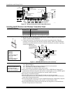
Mounting the PC Board
Alone (no RF Receiver)
Before installing the cabinet's contents, remove the metal cabinet knockouts required for
wiring entry. Do not remove the knockouts after the circuit board has been installed.
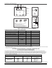
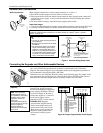
1. Hang two short mounting clips (provided) on the raised cabinet tabs (see Detail B).
2. a. Insert the top of the circuit board into the slots at the top of the cabinet. Make sure
that the board rests on the correct row (see Detail A).
b. Swing the base of the board into the mounting clips and secure the board to the
cabinet with the accompanying screws (see Detail B).
+
+
CIRCUIT
BOARD
DETAIL B
SIDE VIEW
OF MOUNTING
CLIPS
DETAIL A
SIDE VIEW
OF BOARD
SUPPORTING
SLOTS
CIRCUIT
BOARD
MOUNTING-001-V0
CABINET
CABINET
Figure 2. Mounting the PC Board
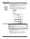
Mounting Board with RF
Receiver
• Do not mount the cabinet on or near metal objects. This will decrease RF range and/or
block RF transmissions from wireless transmitters.
• Do not locate the cabinet in an area of high RF interference (revealed by frequent or
prolonged lighting of the LED in the receiver (random flicker is OK)
1. a. Remove the receiver board from its case, then insert the top of the board into the
slots at the top of the cabinet, as shown in Detail A in Figure 3 on the next page.
Make sure that the board rests on the correct row of tabs.
b. Swing the base of the board into the mounting clips and secure it to the cabinet
with the accompanying screws.
c. Insert the top of the control's board into the slot in the clips and position two clips
at the lower edge of the board.
d. Swing this board into place and secure it with two additional screws.
2. Insert grounding lugs (supplied with the receiver) through the top of the cabinet into
the left-hand terminals of the antenna blocks (at the upper edge of the receiver board)
and secure them to the cabinet top with the screws provided (see Detail B).
3. Insert the receiver's antennas through the top of the cabinet, into the blocks' right-
hand terminals, and tighten the screws.
2-1