


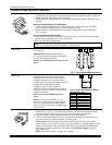


Installing a Keyswitch
Keyswitch Connections
GREEN
RED
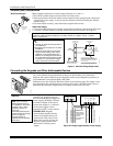
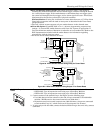
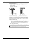
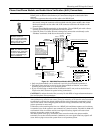
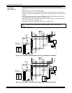
1. Connect the 4146 keyswitch's normally open momentary switch to a zone’s (2-8)
terminals. Remove the 2000 ohm EOL resistor if connected across the selected zone.
2. Using a standard keypad cable as shown:
Connect the yellow and white keyswitch wires to trigger connector pin 3 (+12V).
Connect the Red and Green LED wires to the appropriate output 17/output 18
trigger connector pins.
3. Connect a 2000 ohm EOL resistor across the momentary switch.
4. You can wire an optional closed-circuit tamper switch (model 112) in series with the
zone. If the switchplate is then removed from the wall, the tamper will open,
disabling keyswitch operation until the system is next disarmed from the keypad.
If the tamper is opened when the system is armed, an alarm will occur.
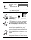
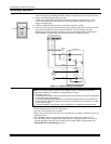
4146 KEYSWITCH
(READY)
GREEN
LOCK
SWITCH (N. O.)
TAMPER
SWITCH (N. C.)
(ARMED)
RED
YELLOW
WHITE
EOLR
(use appropriate value)
11
10
TYPICAL ZONE
ON CONTROL
BOARD
BROWN
BLUE
BROWN
BLUE
820
ohms
820
ohms
00-trigcon-004-V1
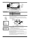
1345678
STANDARD
KEYPAD
CABLE
8-PIN TRIGGER CONNECTOR
KEY
+12 AUX.
OUTPUT 17
OUTPUT 18
(RED)
(YELLOW)
(GREEN)
RED
BLACK
Figure 12. Keyswitch Wiring Connections
Keyswitch Notes
U
L
A UL Listed keyswitch is required for fire installations and UL commercial and residential
burglar alarm installations. The Ademco 4146 keyswitch is UL Listed.
If a keyswitch is used on:
• an installation that transmits opening and closing signals, the keyswitch zone must be programmed
to send opening and closing signals.
• a UL commercial burglar alarm installation, the keyswitch’s tamper switch must be connected in to
the alarm system. This tamper switch zone must also be programmed for Zone Type 05 – Trouble
by Day / Alarm by Night.
• a fire alarm installation, the keyswitch must be located next to an alphanumeric display keypad.
• Use 4146 keyswitch or any N.O. keyswitch.
• Use only one keyswitch per partition.
• When using a keyswitch, the zone it is connected to is no longer available for use as a
protective zone.
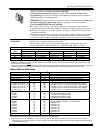
• Use *56 Menu mode to program the keyswitch zone and assign it zone type 77.
• Use *80 Menu mode to program the LED functions: program outputs 17 and 18 for
system operation zone type 78 (red LED) and 79 (green LED) as appropriate (see
Output Device Programming section).
Installation and Setup Guide
2-10