


Sounder (Bell) Connections
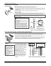
Basic Connections
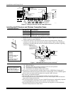
spkr_conn-001-V0
ALARM OUTPUT
10.5 - 13.5 VDC
2A MAX.
3
4
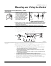
Make sounder connections to alarm output terminals 3 (+) and 4 (–).
• The 12VDC sounder output activates when an alarm occurs.
• Total current drawn from this output cannot exceed 2 amps (going beyond 2 amps will
overload the power supply, or may cause the electronic circuit protecting the sounder
output to trip).
• You must install a battery, since the battery supplies this current.
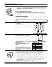
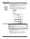
Supervised output
1. Cut the red Bell Supervision Jumper located above terminals 2 and 3 on the PC board.
2. Connect a 2k ohm resistor across the terminals of the last sounder. See Figure 5.
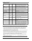
This control complies with NFPA requirements for temporal pulse sounding of fire notification
appliances. Temporal pulse sounding for a fire alarm consists of: 3 pulses – pause – 3 pulses –
pause – 3 pulses–etc..
U
L
• Use only UL Listed sounding devices for
UL installations.
• Bell supervision is required for fire alarm
installations.
• The total current drawn from the alarm
output and the
auxiliary power output,
combined, cannot exceed 600 mA. In
addition, the sounding device must be a
UL Listed audible signal appliance rated
to operate in a 10.2-13.8 VDC voltage
range, and must be mounted indoors.
+
+
2
EXTERNAL ALARM
SOUNDER
TERMINALS ON
CONTROL BOARD
ALARM
OUTPUT
TERMINALS
sounder-001-V0
3
4
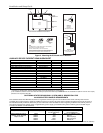
CUT RED JUMPER ON CONTROL
BOARD TO ENABLE BELL
(SOUNDER) SUPERVISION.
2000
OHM
EOL
RESISTOR
IF BELL SUPERVISION IS ENABLED
(RED JUMPER ON CONTROL BOARD IS CUT)
CONNECT A 2000 OHM RESISTOR ACROSS
THE EXTERNAL SOUNDER AS SHOWN BY
THE DOTTED LINE.
DO NOT CONNECT THE RESISTOR AT THE
ALARM OUTPUT TERMINALS THEMSELVES!
OBSERVE
POLARITY
Figure 5. Sounder Wiring (Supervised)
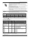
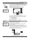
Connecting the Keypads and Other Addressable Devices
Connections
conn-001-V0
RED
GREEN
YELLOW
BLACK
A
R
M
E
D
R
E
A
D
Y
4
_
5
+
6 IN
7 OUT
Connect keypads and other addressable devices (4204, 4219, 4229, 4286, 5881, LRR,
etc.) to the control’s keypad terminals as shown on the Summary of Connections
diagram. The system supports up to 8 keypads, which can be assigned to partitions in
any combination (see program fields *190-*196).
Determine wire size using the Wire Run Chart on the following page. For single 4-wire
runs, determine the current drawn by all units, then refer to the Wiring Run chart to
determine the maximum length that can be safely used for each wire size.
Supplementary Power
(optional)
U
L
Use a UL Listed,
battery-backed supply for
UL installations. The battery
supplies power to these
keypads in case of AC
power loss.
The battery-backed power
supply should have enough
power to supply the
keypads with the UL
required minimum standby
power time.
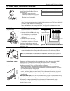
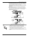
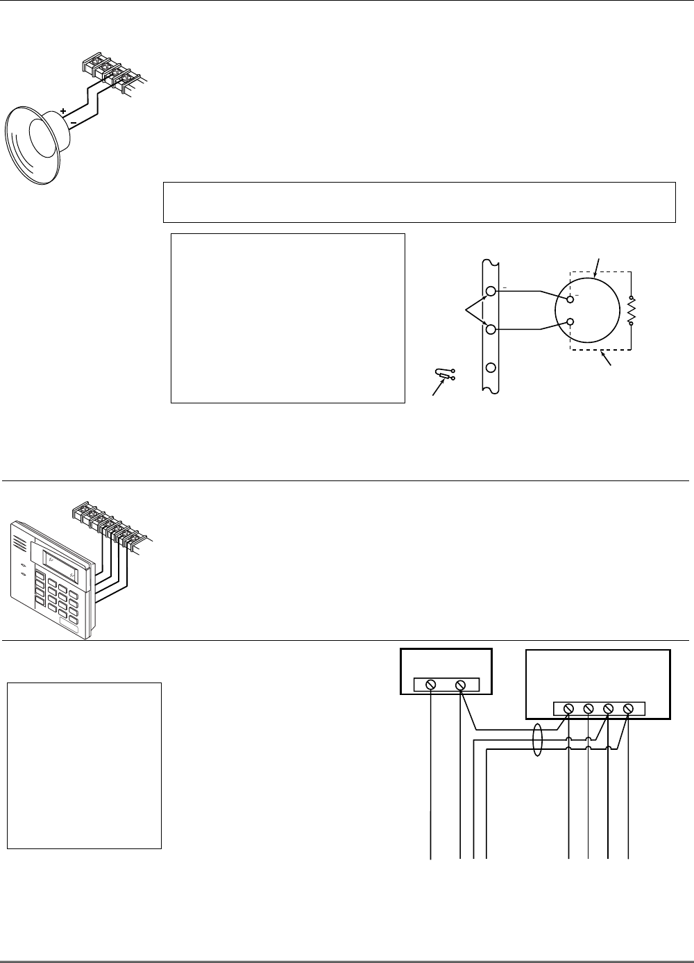
Use supplementary power if the
control’s aux. power load for all
devices exceeds 600mA (suggested
power supply: AD12612). Connect
as shown in Figure 6. Be sure to
connect the negative (–) terminal
on the power supply unit to
terminal 4 (AUX –) on the control.
IMPORTANT: Keypads
powered from supplies that do
not have a backup battery will
not function if AC power is lost.
Make sure to power at least one
keypad in each partition from
the control’s auxiliary power
output.
+
–
+
4567
SUPPLEMENTARY
POWER SUPPLY
–
CONTROL TERMINAL STRIP
AUX.
AUX. DATA
IN
DATA
OUT
IMPORTANT:
MAKE THESE
CONNECTIONS
DIRECTLY TO
SCREW
TERMINALS AS
SHOWN.
TO KEYPAD RED WIRE
TO KEYPAD BLK WIRE
TO KEYPAD YEL WIRE
TO KEYPAD GRN WIRE
TO KEYPAD BLK WIRE
TO KEYPAD RED WIRE
TO KEYPAD GRN WIRE
TO KEYPAD YEL WIRE
supp_pwr_supply-V0
Figure 6. Using a Supplementary Power Supply
Installation and Setup Guide
2-4