


TZ-4 TOTALZONE® ZONE CONTROL PANEL
9 68-0259-1
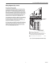
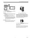
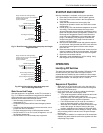
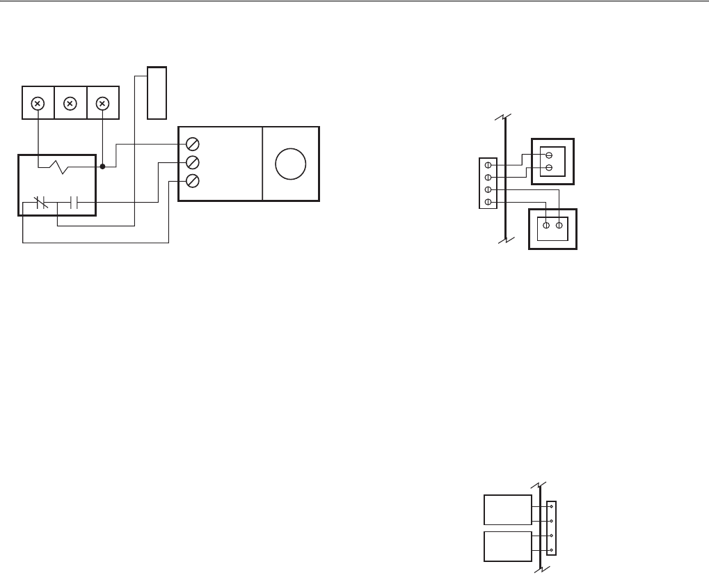
Fig. 12. MARD or ML6161 Damper Motor Actuator using
R8222 Relay wiring.
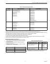
Transformer
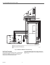
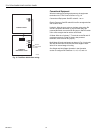
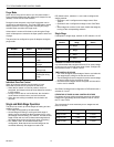
1. Wire the transformers to the panel as shown in Fig. 13.
One 40 VA, 24 Vac transformer controls up to five ARD
or ZD dampers.
2. Connect the transformer to terminals R and C.
3. Add the auxiliary transformer if six to ten ARD or ZD
dampers are used.
a. Wire auxiliary transformer to terminals T1 and T2.
b. It is important that these two transformers be wired
in phase. If they are wired out of phase, the internal
circuit breaker trips and the board de-powers. If this
occurs, remove power, correct the wiring and
restore power to the board.
IMPORTANT
If more than five dampers are required for one zone
or if more than ten dampers are used for the TZ-4,
use the Slave Damper Control Relay (SDCR).
Fig. 13. Wiring transformer(s) to panel.
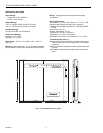
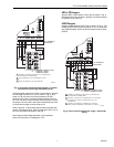
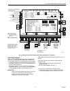
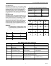
Discharge Air and Outdoor Temperature Sensors
Wire the C7735A Discharge Air Temperature Sensor (DATS)
to the panel as shown in Fig. 14. The Purge LED (yellow)
flashes in all modes except purge if no DATS is connected to
the TZ-4 or if there is a problem with the DATS or the wiring.
For dual fuel applications, connect the C7089 Outdoor
Temperature Sensor as shown in Fig. 14.
Fig. 14. Wiring C7735A Discharge Air Temperature Sensor
(DATS) to panel.
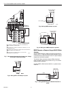
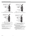
Add-A-Zone Panel
Remove power from TZ-4 before connecting AZ-1 and AZ-2.
Wire the Add-A-Zone (TAZ-4) Panel to the TotalZone (TZ-4)
Panel as shown in Fig.15. Up to seven TAZ-4 Panels can be
wired to one TZ-4 panel to control up to 32 zones.
COM
CCW
CW
ML6161
R8222 RELAY
ZONE CONTROL PANEL
DAMPER TERMINALS
M20548
A
M6 M4 M1
R
C
R
C
T1
T2
C
R
C
R
24 VAC, 40 VA
Transformer
(Required if
more than
four dampers)
24 VAC, 40 VA
Transformer
DAMPER
XFRM
PANEL
XFRM
M20518
M20519
DATS
DATS
DATS
OT
OT
OT
Sensor