


TZ-4 TOTALZONE® ZONE CONTROL PANEL
11 68-0259-1
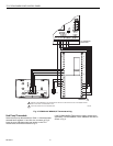
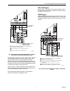
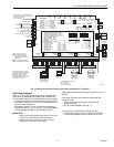
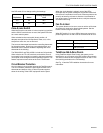
Fig. 16. Wiring conventional heating and cooling equipment to TZ-4 panel.
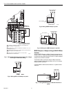
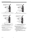
Heat Pump Equipment
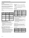
See Fig. 17-22 for heat pump wiring. Refer to manufacturer
instructions for additional wiring details and substitute the
TZ-4 equipment terminals for the thermostat terminals shown.
— Connect the changeover relay to O/B equipment terminal.
— Set switch number 5-7 to on for O (cool) changeover, or to
off for B (heat) changeover.
— Set switch number 5-1 to off for heat pump equipment.
— Set DIP switches 4-1, 4-2, 4-3, and 4-4. See Single Stage
and Multi-Stage Operation in the Operation section.
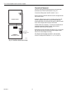
IMPORTANT
Some heat pump manufacturers (such as York and
Trane) use the B terminal as the transformer
common. Do not connect the common from the
equipment to the zone control panel.
Single-Speed Compressor: Wire the compressor to the Y1
terminal.
If the same heat source is used for auxiliary heat and
emergency heat:
— Wire a jumper from W2 (auxiliary heat) to W1/E
(emergency heat).
— Do not connect W3/AUX. See Fig. 17.
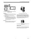
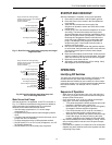
If auxiliary heat is separate from emergency heat:
— Connect the auxiliary heat to W2 jumped to W3/AUX.
— Connect the emergency heat to W1/E. See Fig. 18.
M20520B
ZONE DAMPER MOTORS
M1 - common
M4 - power open
M6 - power closed
HVAC Equipment
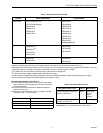
DIP SWITCH S4 SETTINGS
1 2ND STAGE OPERATION: TABLE 1
2 2ND STAGE OPERATION: TABLE 1
3 3RD STAGE OPERATION: TABLE 1
4 3RD STAGE OPERATION: TABLE 1
5 STAGE TIMER: TABLE 2
6 STAGE TIMER: TABLE 2
7 STAGE TIMER: TABLE 2
8 UNUSED
DIP SWITCH S5 SETTINGS
1 SYSTEM TYPE
2 DATS LOW LIMIT
3 PURGE TIME
4 PURGE FAN
5 PURGE DAMPER
6 HEAT FAN
7 O/B ENERGIZED
8 DUAL FUEL
LED STATES:
Heat LED Heating Mode
Flashing Heat LED High Limit
Cool LED Cooling Mode
Flashing Cool LED Low Limit
Purge LED Purge Mode
Flashing Purge LED Sensor Failure
Fan LED Fan Mode
EM Heat LED EM Heat Mode
TABLE 1
#1/#3 #2/#4 OPERATION
1 1 STAT
1 0 TIMER
0 1 % ZONES
0 0 OFF
TABLE 2
#5 #6 #7 TIME
1 1 1 5 MIN
1 1 0 10 MIN
1 0 1 15 MIN
1 0 0 20 MIN
0 1 1 30 MIN
0 1 0 40 MIN
0 0 1 50 MIN
0 0 0 60 MIN
ON OFF
1 0
CONV HP
40F 48F
2.0 MIN 3.5 MIN
HVAC PANEL
NO CHG OPEN
HVAC PANEL
COOL HEAT
DISABLED ENABLED
R
H
R
C
W
1
/E
W
2
W
3
/AUX
ZONE LEDs
ON Damper open or opening
OFF Damper closed or closing
MOMENTARY PUSH BUTTONS
Boot – Clears microprocessor
Purge Overide – Bypass Purge Mode
BOOT
PURGE
OVERRIDE
Single Transformer Heating/Cooling
systems require a jumper to be installed
connecting R
H
and R
C
(factory installed).
1 “C” terminal connection
is not required on battery
powered, power stealing,
or some electromechanical
thermostats.
2 Leave jumper disconnected
for conventional thermostats.
R
C
T1
T2
AZ2
AZ1
OFF
ON
EM
Heat
Unoccup
Occup
Zone-
A-Lone
Y
1
Y
2
G
O/B
Heating Transformer
24 VAC
Equip.
Cooling Transformer
First Stage Heating
Second Stage Heating Relay
Third Stage Heating
First Stage Cooling Relay
Second Stage Cooling Relay
Fan Relay
T
his diagram shows the typical
t
hree-stage equipment, thermostat,
a
nd damper motor connections.
F
or specific wiring for other
t
hermostats, damper motors, and
H
VAC Equipment, refer to the
nstallation Instructions.
M6 M4M1
DATS
DATS
1
Zone 4 Thermostat
C R
C
R
Power-closed
Spring-open
(Model ZD)
Power-closed
Spring-open
(Model ARD)
Power-closed
Spring-open
(Model ARD)
24VAC, 40VA
Transformer
(Required if
more than
four dampers
)
24VAC, 40VA
Transformer
OC
OC
Remote
Zone-A-Lone
Add-A-Zone
Panel(s)
DAMPER
XFRM
PANEL
XFRM
HEAT COOL PURGE FAN EM. HEAT ZONE 1 ZONE 2 ZONE 3 ZONE 4
DIP SWITCH S4 DIP SWITCH S5
1
O
N
2 3 4 5 6 7 81
O
N
2 3 4 5 6 7 8
M6 M4M1
1
Zone 3 Thermostat
M6 M4M1
1
Zone 2 Thermostat
456Z
123X
Power-open
Power-closed
(Opposed Blade
Damper Motors)
O/BY2GW2M6M4M1
W3/
AUXY1
W1/
ERC
Y1 W3/
AUX
W2W1RCY2GLO/B Y1 W3/
AUX
W2W1RCY2GLO/B Y1 W3/
AUX
W2W1RCY2GLO/B Y1 W3/
AUX
W2W1RCY2GLO/B
L
O/BY2GW2
W3/
AUXY1
W1/
ERC
L
O/BY2GW2
W3/
AUXY1
W1/
ERC
L
O/BY2GW2
W3/
AUXY1
W1/
ERC
L
1
Zone 1 Thermostat
ZONE 1
2
Thermostat
DATS
OT
OT
OT
Sensor
130 F
120 F
110 F
140 F
150 F
160 F
MAX. DUCT TEMP.
25 F
20 F
15 F
35 F
30 F
40 F
45 F
DUAL FUEL OT SETTING
Damper
ZONE 2
2
Thermostat Damper
ZONE 3
2
Thermostat Damper
ZONE 4
2
Thermostat Damper