


TZ-4 TOTALZONE® ZONE CONTROL PANEL
68-0259-1 12
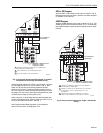
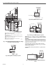
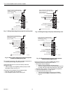
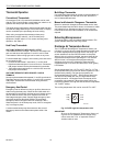
Fig. 17. Wiring single-stage heat pump with auxiliary heat.
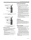
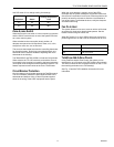
Fig. 18. Wiring single-stage heat pump with separate
auxiliary and emergency heat.
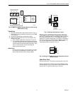
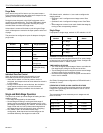
Two-speed Compressor: Wire the first stage compressor to
Y1 and the second stage compressor to Y2.
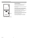
If the same heat source is used for auxiliary heat and
emergency heat:
— Wire a jumper from W3/AUX (auxiliary heat) to W1/E
(emergency heat), see Fig. 19.
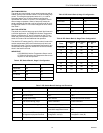
If auxiliary heat is separate from emergency heat:
— Wire the auxiliary heat to W3/AUX.
— Wire emergency heat to W1/E, see Fig.20.
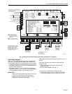
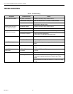
Fig. 19. Wiring two-stage heat pump with auxiliary heat.
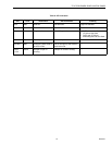
Fig. 20. Wiring two-stage heat pump with separate
auxiliary and emergency heat.
Dual Fuel Heat Pumps: Install C7089B1000 Outdoor
Temperature Sensor to terminals OT and OT.
— Set outdoor sensor setting to:
— Balance point temperature of heat pump or
— Outdoor temperature above which the heat pump is to
be used and below which the fossil fuel is to be used.
— Set DIP switch number 5-8 to off for dual fuel operation.
— Connect compressor to Y1. See Fig. 21.
— Connect fossil fuel heat to W1/E.
— Connect second stage of fossil fuel to W3/AUX.
— Connect second stage of compressor to Y2. See
Fig. 22.
M20521B
HVAC Equipment
R
H
R
C
W
1
/E
W
2
W
3
/AUX
Single Transformer Heating/Cooling
systems require a jumper to be installed
connecting R
H
and R
C
(factory installed).
Y
1
Y
2
G
O/B
Heating Transformer
24 VAC
Equip.
Cooling Transformer
Auxiliary Heat
Compressor
Reversing Valve
Fan Relay
1
1
FIELD INSTALLED JUMPER.
M20522B
HVAC Equipment
R
H
R
C
W
1
/E
W
2
W
3
/AUX
Single Transformer Heating/Cooling
systems require a jumper to be installed
connecting R
H
and R
C
(factory installed).
Y
1
Y
2
G
O/B
Heating Transformer
24 VAC
Equip.
Cooling Transformer
Emergency Heat
Auxiliary Heat
Compressor
Reversing Valve
Fan Relay
1
FIELD INSTALLED JUMPER.
1
M20523B
HVAC Equipment
R
H
R
C
W
1
/E
W
2
W
3
/AUX
Single Transformer Heating/Cooling
systems require a jumper to be installed
connecting R
H
and R
C
(factory installed).
Y
1
Y
2
G
O/B
Heating Transformer
24 VAC
Equip.
Cooling Transformer
Auxiliary Heat
First Stage Compressor
Second Stage Compressor
Reversing Valve
Fan Relay
1
1
FIELD INSTALLED JUMPER.
M20524
A
HVAC Equipment
R
H
R
C
W
1
/E
W
2
W
3
/AUX
Single Transformer Heating/Cooling
systems require a jumper to be installed
connecting R
H
and R
C
(factory installed).
Y
1
Y
2
G
O/B
Heating Transformer
24 VAC
Equip.
Cooling Transformer
Emergency Heat
Auxiliary Heat
First Stage Compressor
Second Stage Compressor
Reversing Valve
Fan Relay