TZ-4 TOTALZONE® ZONE CONTROL PANEL
17 68-0259-1
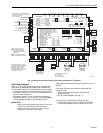
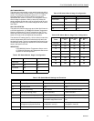
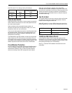
Use DIP switch 5-2 to change cooling limit settings:
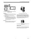
Zone-A-Lone Switch
When the Zone-A-Lone switch is in the occupied (up) position
and the OC/OC terminals are not used, the system functions
as a zone control system.
When switched to the unoccupied (down) position, all
dampers are opened and all requests for heat, cool, or fan,
except from zone one, are not honored.
The zone one thermostat becomes the controlling thermostat
for the entire system. During long unoccupied periods, one
thermostat can be set back instead of adjusting each zone
thermostat in the building.
The T8601D2027 and T8611G2051 include two OC terminals.
When wired to the TZ-4 OC terminals, and with the Zone-A-
Lone switch in the occupied (up) position, the board enters the
unoccupied mode during the Leave and Sleep programs. This
feature requires two extra wires to the Zone 1 thermostat.
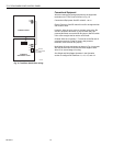
Circuit Breaker Protection
A built-in thermal circuit breaker protects the TotalZone panel.
This circuit breaker protects the panel against shorts in the
thermostat and damper wiring. It does not protect against
shorts in the wiring of the HVAC equipment into the panel.
When the circuit breaker is tripped, none of the LEDs
illuminate and the yellow rectangular component located left
of the R and C terminals is hot to touch. Remove power to the
panel for at least five minutes to allow the circuit breaker to
cool off and reset. To eliminate the short, verify the dampers
and thermostat wiring.
Fan On In Heat
The system blower can be set to come on with a call for heat
as required for hydro-air or electric heat systems. Set the
blower function using DIP switch 5-6.
When DIP switch 5-1 is set to Off for heat pump control, the
panel brings the fan on with a call for heat and a call for cool.
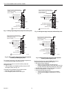
TotalZone Add-A-Zone Panels
Using TotalZone Add-A-Zone Panels, the system can be
expanded to up to 32 zones using TAZ-4 Add-A-Zone panels.
Two wires connect the AZ1 and AZ2 terminals on the TZ-4 to
the matching terminals on the TAZ board(s).
See Fig. 15 and the TAZ installation instructions for more
information.
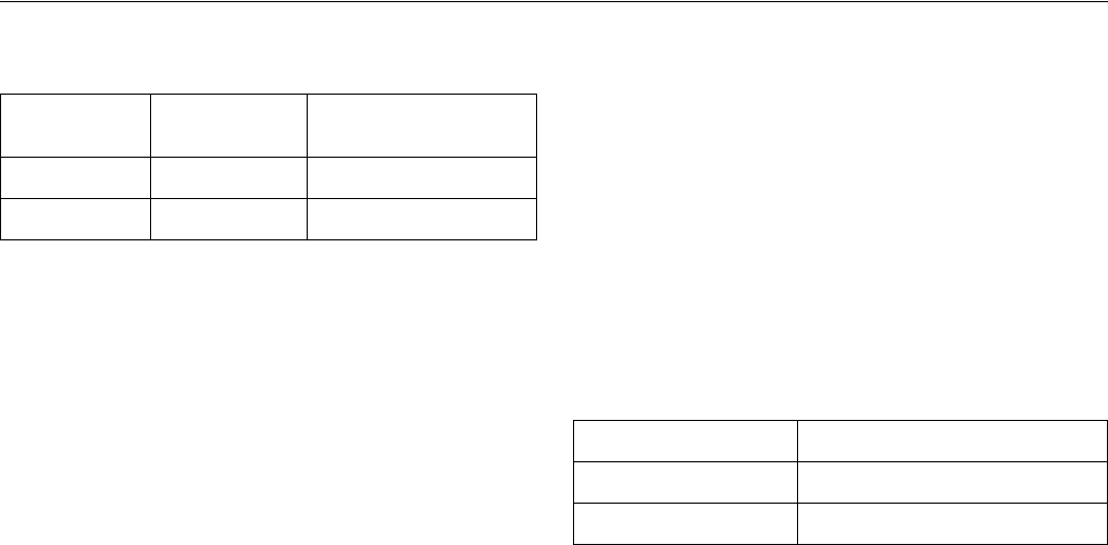
Dip Switch Status
Cooling Temperature
Limit
5-2 On 40°F
5-2 Off 48°F
DIP Switch 5-6 Fan Control
On HVAC system
Off Fan on in heat


