


VisionPRO
TM
8000 Touchscreen Programmable Thermostat
33 68-0280—01
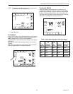
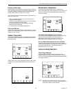
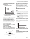
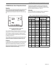
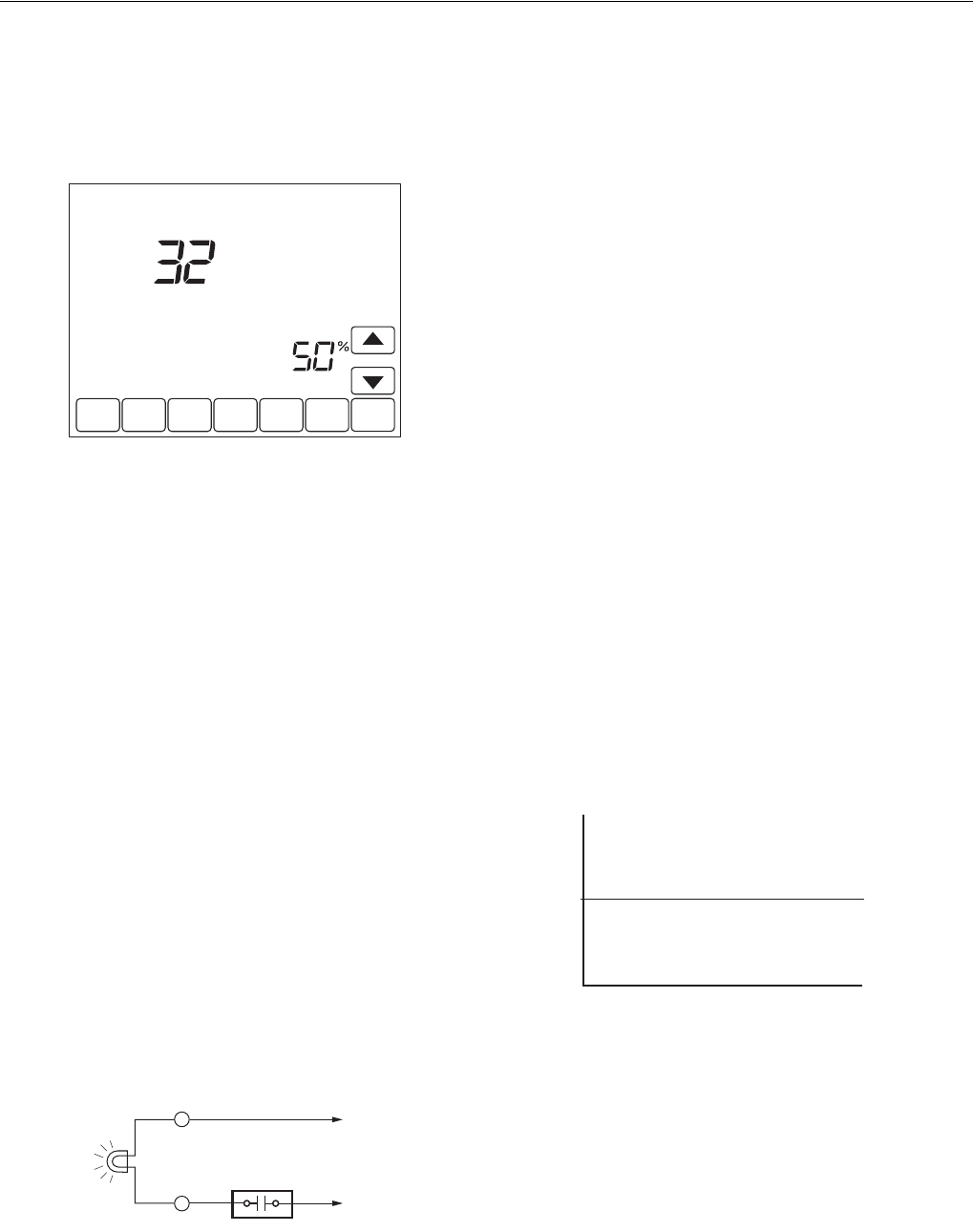
Control Dehumidification Setting (Select Models)
Select models read the inside humidity level and allow for a
dehumidification setting:
1. Press the More key until the inside humidity percent and
dehumidification setpoint are shown.
2. Use Up and Down arrow keys, located to the right of the
dehumidifier setpoint, to set desired humidity level for
dehumidification in the summer.
3. Press Done key.
Dehumidification Droop Control
The dehumidification control attempts to control to the user's
humidity setpoint by turning on the air conditioner. In
extremely high humidity conditions, the thermostat keeps the
air conditioner running (energizing Y and G) for up to 3°F
below the temperature setpoint. It does this while trying to
achieve the desired humidity setpoint and balancing that with
the temperature setpoint. The thermostat controls up to 3° F
below the temperature setting until either the humidity is
satisfied or conditions change.
Special Heat Pump Operation
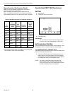
Heat Pump LED Indication (Requires 24 Vac
Common Connection)
A red LED indication is located in the upper right corner of the
thermostat. It is only visible when lighted.
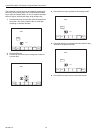
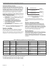
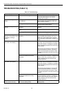
When the L terminal is wired to an equipment monitor, the
LED signals when a check or fail signal is sent to the
thermostat from the system. This is operational in the Heat,
Off, Cool or Auto positions. See Fig. 32.
Fig. 32. L terminal switch to R (power) side of system
transformer.
Heat Pump Emergency Heat LED Indication
(Requires 24 Vac Common Connection)
The thermostat uses a red LED indicator that lights when the
thermostat is in the Emergency Heat mode. The LED is
located in the upper right corner of the thermostat. It is visible
only when on. When the thermostat is in the Em. Heat system
mode, the L terminal is continuously energized and the LED is
on.
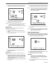
Heat Pump Temperature Lockouts
Dual Fuel Heat Pump and Outdoor Temperature
Sensor
In this operation, there is no external fossil fuel kit (dual fuel
kit) installed; the thermostat controls this function.
1. Choose correct heat pump application in Installer Setup
Number 0170.
2. Choose Fossil Fuel Option as the backup heat source
in Installer Setup Number 0200.
3. Choose No External Fossil Fuel Kit Option is control-
ling back up heat in Installer Setup Number 0210.
4. Choose Outdoor Temperature Sensor for Heat Pump
Temperature Lockouts Option in Installer Setup Num-
ber 0340.
5. Choose appropriate Balance Point Temperature in
Installer Setup Number 0350.
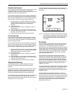
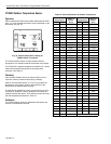
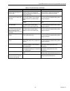
OPERATION IN HEAT MODE ABOVE BALANCE POINT (OUTDOOR
TEMPERATURE)
When the outdoor temperature is above the selected Balance
Point Temperature (ISU 0350), only the compressor operates
and the fan (G terminal) energizes when the thermostat calls
for heat. See Fig. 33.
Fig. 33. Dual Fuel Heat Pump Operation in Heat mode with
Balance Point Set.
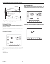
OPERATION IN HEAT MODE BELOW BALANCE POINT (OUTDOOR
TEMPERATURE)
When the outdoor temperature is below the selected Balance
Point Temperature (ISU 0350), only the Fossil Fuel (auxiliary
heat) operates and the fan (G terminal) does not energize
when the thermostat calls for heat.
DONE CANCEL
DEHUMIDIFIER
Inside
Humidity
M19967
M19907
EQUIPMENT
MONITOR
L TO R
TO C
C
30
M22441
BALANCE
POINT
COMPRESSOR ONLY
FOSSIL FUEL ONLY
OUTDOOR TEMPERATURE