VisionPRO
TM
8000 Touchscreen Programmable Thermostat
13 68-0280—01
Locate and Mount C7189U Remote Indoor
Temperature Sensor (Optional)
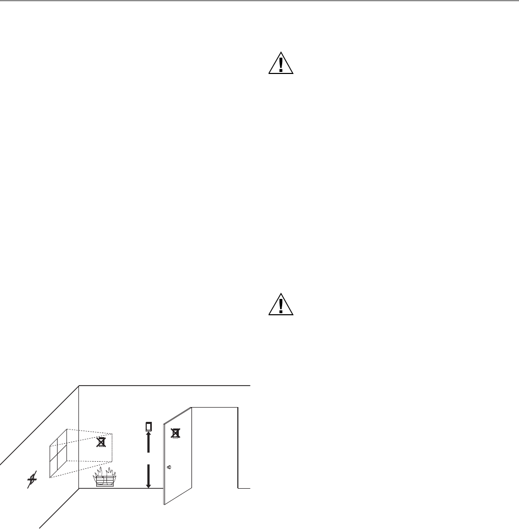
1. Choose a location (see Fig. 27) for mounting the sensor
on an inside wall about 5 ft (1.5m) above the floor. A
vertically-mounted standard 2 x 4 in. (51 x 102 mm)
junction box can also be used.
2. Be sure wire distance between C7189 and thermostat is
less than 200 feet.
3. Make sure there is good air circulation at average
temperature at the chosen location. Avoid the following
locations because they can introduce errors in sensor
measurements. See Fig. 27.
a. Hot areas caused by:
(a) Concealed pipes or ducts.
(b) Drafts from fireplaces or other heat sources.
(c) Convection or radiant heat from the sun or
electrical equipment.
b. Cold areas caused by:
(a) Concealed pipes or ducts.
(b) Drafts from windows and doors.
(c) Unheated areas on the other side of the wall
location.
c. Dead air areas:
(a) Behind doors, furniture and curtains.
(b) In corners and alcoves.
4. Mark the area on the wall selected for mounting the
C7189 Sensor or junction box.
5. Run wire cable to a hole at the selected wall location.
Pull approximately three inches of wire through the
opening. Color-coded, 18-gauge thermostat wire is
recommended.
Fig. 27. Typical location for C7189 Indoor Sensor.
Wire C7189 Indoor Sensor
Electrical Interference (Noise) Hazard.
Can cause erratic system operation.
Keep wiring at least one foot away from large inductive
loads such as motors, line starters, lighting ballasts
and large power distribution panels.
IMPORTANT
Erratic temperature readings from a sensor can
occur as a result of any of the wiring practices
described below. Avoid these practices to assure
correct operation.
— Be sure wires have a cable separate from the
thermostat cable.
— Do not route temperature sensor wiring with building
power wiring, next to control contactors or near light
dimming circuits, electric motors or welding
equipment.
— Avoid poor wiring connections.
— Avoid intermittent or missing building earth ground.
Electrical Shock Hazard.
Can cause electrical shock or equipment damage.
Disconnect power supply before connecting wiring.
Wiring must comply with applicable codes, ordinances and
regulations.
1. Wire C7189 Indoor Sensor to S1and S2 terminals on
the thermostat. For an example of general wiring of
C7189, see Fig. 28 to wire one sensor and 29 to wire
multiple sensors.
2. Push excess wire back into the hole. Plug the hole
using nonhardening caulk, putty or insulation to prevent
drafts from affecting performance.
3. Remove C7189 cover.
4. Mount C7189 to the wall or junction box using the
screws and anchors provided.
5. Level the C7189 for appearance only. Device functions
correctly even when not level.
6. Install C7189 cover.
5 FEET
(1.5 METERS)
YES
NO
NO
NO
M4476


