


TB7220 COMMERCIALPRO™ PROGRAMMABLE THERMOSTAT
9 63-2635—03
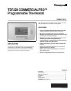
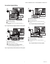
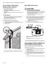
Fig. 20. Typical hookup of single-stage heat pump with
auxiliary heat (2H/1C).
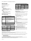
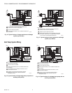
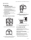
Fig. 21. Typical hookup of multistage heat pump
with auxiliary heat (3H/2C).
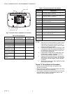
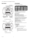
POWER THE THERMOSTAT
You can choose from three methods to power the thermostat:
• Batteries only (AAA alkaline).
• 24 Vac direct connection only.
• 24 Vac direct connection with battery backup (AAA alkaline).
Wiring 24 Vac Common
• Single-Transformer System—Connect the common side of
the transformer to the C screw terminal of the thermostat
wallplate. Leave the metal jumper wire in place between Rc
and R.
• Two-Transformer System—Connect the common side of
the cooling transformer to the C screw terminal of the
thermostat wallplate. Remove the metal jumper wire
between Rc and R.
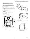
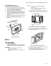
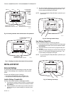
Installing Batteries
1. Install two AA alkaline batteries on the back of the ther-
mostat as marked. See Fig. 22.
Fig. 22. Installing batteries.
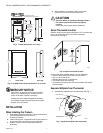
2. Locate and remove tab labeled Remove. See Fig. 23.
IMPORTANT
This tab must be removed in order to set the real-time
clock.
Fig. 23. Remove tab labeled REMOVE from thermostat
back.
COMPRESSOR CONTACTOR
ECONOMIZER
M23020
CHANGEOVER VALVE
1
2
3
4
5
FAN RELAY
POWER SUPPLY. PROVIDE DISCONNECT MEANS AND OVERLOAD
PROTECTION AS REQUIRED.
FACTORY INSTALLED JUMPER.
WHEN USING BATTERIES, THE 24V COMMON CONNECTION
IS OPTIONAL.
"O/B" TERMINAL SET TO CONTROL AS EITHER "O" OR "B"
IN THE INSTALLER SETUP.
OPTIONAL OUTDOOR OR INDOOR REMOTE SENSOR.
WIRES MUST HAVE A CABLE SEPARATE FROM THE
THERMOSTAT CABLE.
OUTDOOR/INDOOR
TEMPERATURE
SENSOR
3
L1
(HOT)
L2
1
24 VAC
5
AUXILIARY HEAT RELAY
C
G
Y
O/B
RC
R
W1
Y2
A
S1
S2
4
2
COMPRESSOR 1
COMPRESSOR 2
M23021
CHANGEOVER VALVE
FAN RELAY
1
2
3
4
5
POWER SUPPLY. PROVIDE DISCONNECT MEANS AND OVERLOAD
PROTECTION AS REQUIRED.
FACTORY INSTALLED JUMPER.
WHEN USING BATTERIES, THE 24V COMMON CONNECTION
IS OPTIONAL.
"O/B" TERMINAL SET TO CONTROL AS EITHER "O" OR "B"
IN THE INSTALLER SETUP.
OPTIONAL OUTDOOR OR INDOOR REMOTE SENSOR.
WIRES MUST HAVE A CABLE SEPARATE FROM THE
THERMOSTAT CABLE.
OUTDOOR/INDOOR
TEMPERATURE
SENSOR
3
L1
(HOT)
L2
1
24 VAC
5
ECONOMIZER
AUXILIARY HEAT RELAY
C
G
Y
O/B
RC
R
W1
Y2
A
S1
S2
4
2
M22259
BACK OF THERMOSTAT
BATTERY HOLDER
BATTERIES (2)
REMOVE
TAB
REMOVE DURING
INSTALLATION
M22260
REMOVE DURING
INSTALLATION