


TB7220 COMMERCIALPRO™ PROGRAMMABLE THERMOSTAT
63-2635—03 20
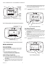
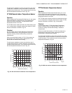
NOTE: There is a 5°F deadband between Compressor and
Auxiliary Heat lockout temperatures
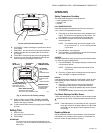
Operation in Heat Mode
When the outdoor temperature is:
— Below Compressor Lockout Temperature: only Auxiliary
Heat operates.
— Above Auxiliary Lockout Temperature: only the Compressor
operates.
— Between the two temperatures: both the Compressor and
Auxiliary Heat operate.
Fig. 41. Heat Pump Operation with Lockout Temperatures
Set.
Operating Sequence
The thermostat energizes specific terminal(s), depending on
the demand for heating, cooling or fan. The thermostat screen
shows the time, inside temperature, system and fan selections.
Additional indicators are shown when the heating, cooling or
fan is energized. See Tables 9 and 10 for specification
information.
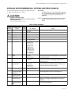
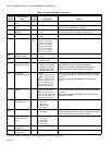
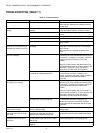
Table 9. Sequence of Operation for Conventional Systems.
a
If Installer Setup System type is set to two stages of cooling.
b
G energizes only if Installer Setup 0180 is set to Electric.
c
If Installer Setup System type is set to two stages of heating.
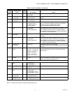
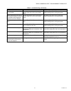
Table 10. Sequence of Operation for Heat Pump Systems.
a
Configure O/B in Installer Setup. Based on last piece of
equipment called (cooling = O; heating = B).
b
If Installer Setup System Type is set to 3Heat/2Cool Heat
Pump with Auxiliary Heat.
c
If Installer Setup System Type is set to 2Heat/1Cool Heat
Pump with Auxiliary Heat.
d
This terminal does not energize if Installer Setup System type
is set to 2 Heat/2 Cool Heat Pump with no Auxiliary Heat.
Second Stage Heat and Cool Control
While maintaining setpoint, several factors affect when 2nd
stage energizes such as load conditions, environmental
conditions, P+I control, and home insulation. The second stage
energizes when the thermostat senses 1st stage is running at
90% capacity. This operation is droopless control.
Temperature Sensor Operation and Checkout
Allow outdoor or indoor temperature sensor to absorb the air
for a minimum of five minutes before taking a reading. See the
Sensor instructions for more information.
NOTE: The C7089U, C7189U, and T7770A Temperature
Sensors are calibrated at the factory and cannot
be recalibrated in the field.
C7089U Outdoor Temperature Sensor
Operation
When installed with Thermostat ISU 0340 set to 1 or 2, the
thermostat can display outside temperature.
Checkout
Allow C7089U Outdoor Sensor to absorb outdoor air for a
minimum of twenty minutes before taking a reading.
With an accurate thermometer (±1°F [0.5°C]) measure the
temperature at the sensor location, allowing time for the
thermometer to stabilize before reading.
System
Setting
Fan
Setting Call for Action
Energize
Terminals
Screen
Message
Off Auto — — —
Cool Auto — — —
Cool
or Auto
Auto Stage 1
Cooling
Y, G Cool On
Cool
or Auto
Auto Stages 1 and 2
Cooling
Y, Y2
a
, G
Cool On
Heat Auto — — —
Heat
or Auto
Auto Stage 1
Heating
W, G
b
Heat On
Heat
or Auto
Auto Stages 1 and 2
Heating
W, W2
c
, G
b
Heat On
35
M19950
COMPRESSOR
LOCKOUT
TEMPERATURE
AUXILIARY
LOCKOUT
TEMPERATURE
COMPRESSOR ONLY
BOTH COMPRESSOR AND
AUXILIARY HEAT
AUXILIARY ONLY
50
OUTDOOR TEMPERATURE
System
Setting
Fan
Setting Call for Action
Energize
Terminals
Screen
Message
Off Auto —
O/B
a
—
Cool
Cool
or Auto
Auto Stage 1 Cooling
Y, G, O/B
a
Cool On
Stages 1 and 2
Cooling
Y, Y2
b
, G,
O/B
a
Heat Auto None
O/B
a
—
Heat
or Auto
Auto Stage 1 Heating
Y, G, O/B
a
Heat On
Stages 1 and 2
Heating
Y, W1
c
, G,
O/B
a
Auxiliary
Heat On
Stages 1, 2 and 3
Heating
Y, Y2
b
,
W1
d
, G,
O/B
a