


T874 MULTISTAGE THERMOSTATS AND Q674 SUBBASES
9 60-2485—8
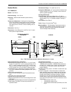
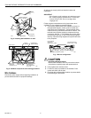
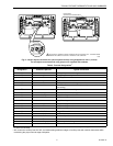
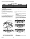
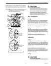
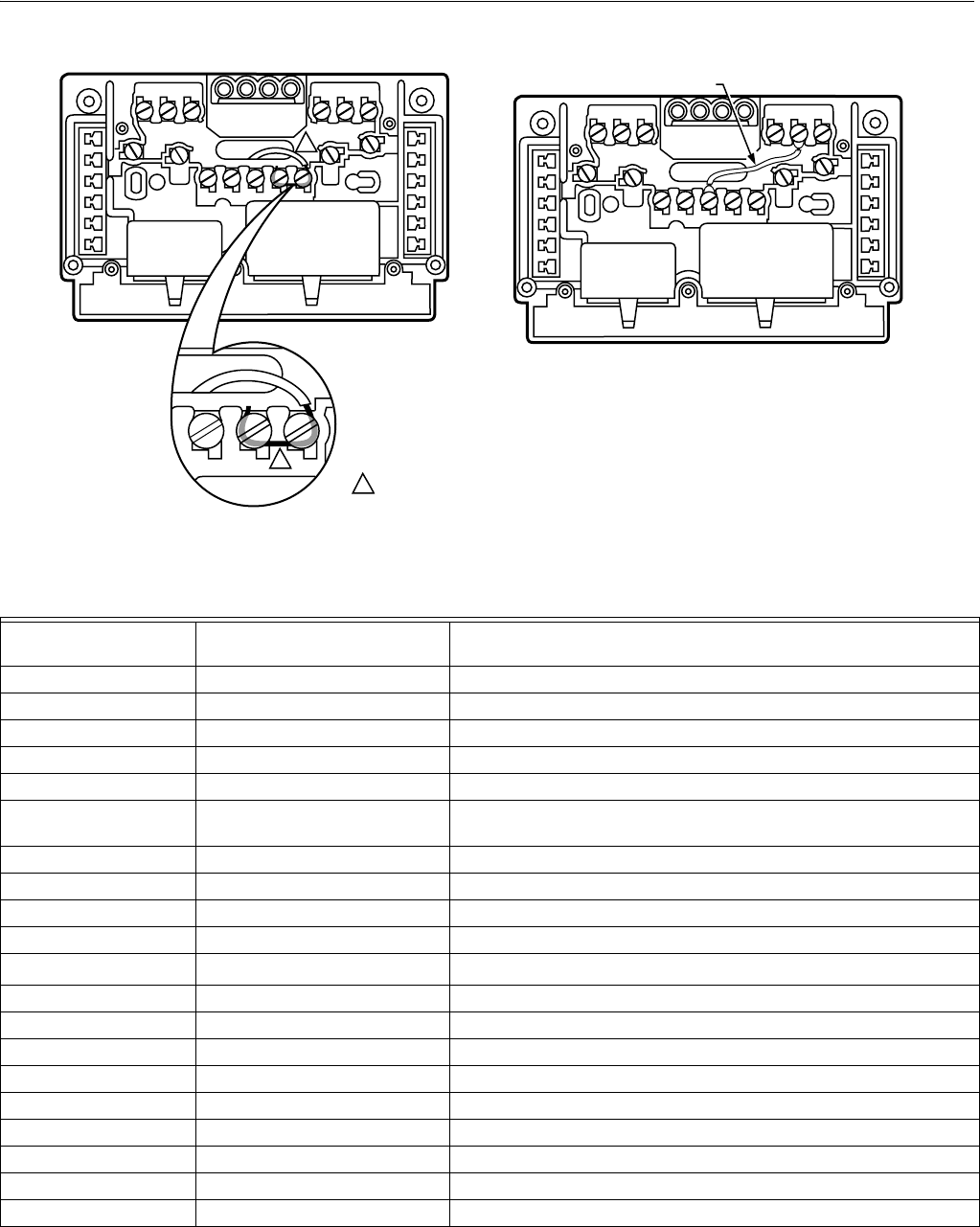
Fig. 8. Jumper adjacent terminals for special system hookup using stripped wire 3/4 in. (19 mm).
For nonadjacent terminals and using jumper wire supplied with subbase.
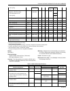
Table 5. Terminal Designations
a
Standard Terminal
Designation
Alternate Designations or
Customer Specials Typical Connection
B Heating damper motor; changeover valve
E K Emergency heat relay
G F Fan relay coil
L System monitor
O R Cooling damper motor; changeover valve
R V Power connection to transformer (internally connected for heating
and cooling)
RC Power connection to cooling transformer
RH Power connection to heating transformer
W1 H1, R3 Stage 1 heating control
W2 H2, Y, R4 Stage 2 heating control
W3
Stage 3 heating control
b
Y1 C1, M Stage 1 cooling control
Y2 C2 Stage 2 cooling control
Y3 Stage 3 cooling control
X X1,X2,C Clogged filter switch or common connection
T A Outdoor thermistor
L, C, H HSII control panel
PDefrost
O Momentary circuit, changeover
A, A1, A2, Z, C, L LEDs
a
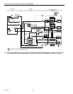
Other terminal designations can be used that are not listed on this table. Refer to the hookup drawing and internal schematic
for exact connections.
b
W3 controls the auxiliary heat like W2, and allows adding additional stages of auxiliary heat with outdoor thermostats while
maintaining the proper second stage anticipation.
M5899
1
1
1 TWO ADJACENT TERMINALS SHOWN JUMPERED ARE FOR EXAMPLE ONLY. COMPARE WIRING
DIAGRAM AND SUBBASE TO IDENTIFY TERMINALS TO BE JUMPERED.
JUMPER WIRE
(SUPPLIED WITH SOME MODELS)