T874 MULTISTAGE THERMOSTATS AND Q674 SUBBASES
27 60-2485—8
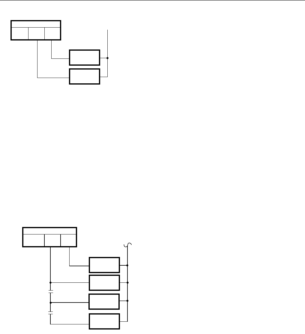
Fig. 39. Auxiliary heat in two-stage thermostat.
This method keeps the auxiliary heat off until the heating load
is large enough to demand 100 percent heat pump operation.
That demand is measured by the thermostat and is the actual
heat requirement of the space. The two-stage thermostat
requires about a 2°F (1.1°C) room temperature drop to bring
on the second stage.
Stage or Time Modulated Control
There are two different ways to control auxiliary heat, staged
or time modulated control.
Outdoor thermostats are used to switch additional increments
of electric heat into the thermostat circuit as the outdoor
temperature gets lower. All increments of auxiliary heat are
still controlled by stage-two of the thermostat but only if the
outdoor temperature requires the additional capacity. See
Fig. 40.
Fig. 40. Outdoor thermostats for auxiliary heat.
The rationale for this system is that it very closely matches the
system capacity to the heating load of the building. By
calculating the heat loss of a building, the installing contractor
can pick the theoretical outdoor temperature at which to
permit each additional unit of electric heat to be operated by
the second stage of the room thermostat.
The disadvantage of this system is that it can require several
outdoor thermostats. Also, since the unit is operating most
often at nearly full capacity, the thermostat is on longer which
results in more droop, with a little more offset from the
thermostat setpoint.
In addition, the capacity is tied to theoretical load, based on heat
loss calculations. Normally this is very close to the actual load,
but there are times where the second stage is switched on too
soon (no harm done) or too late (the building gets cold).
The T874 Thermostat produces time modulated control, which
is the on time of the thermostat changing during each cycle as
the load changes. The on time of the heating system is
directly proportional to the heating load of the building. As an
example of the quality of time modulated control, consider the
typical gas furnace. It can have a capacity of 100,000 Btu
(293 kW), which is controlled On-Off. The output is 100,000 Btu
(293 kW) or nothing. A quality thermostat controls so closely that
the occupants rarely detect changes in room temperature.
The same is true with 50,000 or 60,000 Btu (146.5 or
178.8 kW) of heat pump auxiliary electric heat. The T874 can
provide the same high quality control.
This scheme also eliminates the need for outdoor thermostats
and thus offers the manufacturer an opportunity to reduce unit
cost. One disadvantage is that a thermostat jiggler can be
demanding more kW of strip heat when chilly.
The method any particular manufacturer selects depends on
which arguments it finds persuasive and the opinions of its
distributors and dealers.
Three-Stage Thermostat
A definite improvement in quality of control and economy can
be achieved with a three-stage thermostat (T874W), which is
especially true with heat pumps using dual compressors.
Three-stage control permits both the heat pump and the
auxiliary heat to be tied directly to the demand of the
controlled space. With a two-stage compressor, maximum
(100 percent) heat pump operation is required before auxiliary
heat is brought on.
Emergency Heat
Some provision is generally required to back up the compressor
in the event of a failure during the heating season. In fact, it is
quite common to find that local building codes or electric utilities
require that a specified percent of the building heating
requirements be available from emergency heat—a source
other than the heat pump compressor. Almost universally, the
source is electric resistance heaters. Typically, the requirement
is for 70 or 80 percent of the building heating needs.
Switching to Emergency Heat
Conventional heat pump control (thermostat logic) usually
includes a manual subbase switch to bring on the emergency
heat.
In one control strategy, the emergency heat relay is turned on
by the EM.HT. selector switch on the thermostat subbase. The
compressor is prevented from running. The electric heaters
are cycled as they normally would be by the second stage of
M583
COMPRESSOR
CONTRACTOR
THERMOSTAT
HEAT 2
HEAT 1
AUXILIARY
HEAT RELAY
CONTROLS
AT 65°F (18°C
CONTROLS
AT 63°F (17°C)
COMPRESSOR
CONTACTOR
THERMOSTAT
HEAT 2
HEAT 1
AUXILIARY
HEAT RELAY 1
AUXILIARY
HEAT RELAY 2
AUXILIARY
HEAT RELAY 3
UTDOOR
HERMOSTATS
20°F
(-7°C)
5°F
(-15°C)
