


T874 MULTISTAGE THERMOSTATS AND Q674 SUBBASES
60-2485—8 8
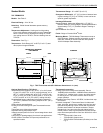
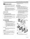
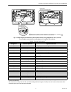
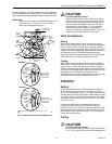
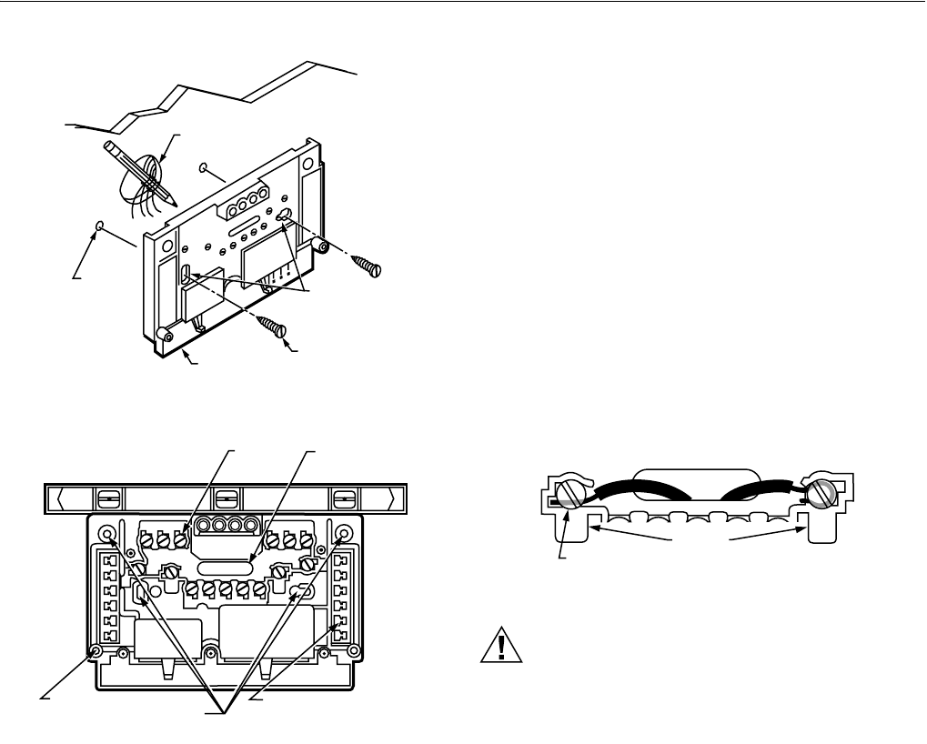
Fig. 5. Installing Q674 Subbase on wall.
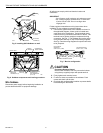
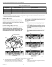
Fig. 6. Subbase components and leveling procedure.
Wire Subbase
Disconnect power supply before beginning installation to
prevent electrical shock or equipment damage.
All wiring must comply with local electrical codes and
ordinances.
IMPORTANT
Use 18 gauge, solid-conductor wire whenever possi-
ble. If using 18 gauge stranded wire, no more than
10 wires can be used. Do not use larger than
18 gauge wire.
Follow equipment manufacturer wiring instructions when
available. To wire subbase, proceed as follows:
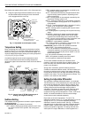
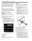
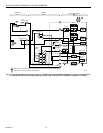
1. Connect the system wires to the subbase as shown in
the applicable diagram. A letter code is located near
each terminal for identification. Typical terminal desig-
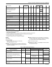
nation and wiring connections are listed in Table 5. The
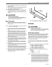
terminal barrier permits straight or wraparound wiring
connection. See Fig. 7. The subbase can require one or
more jumpers that may or may not be factory-supplied.
See Fig. 8 and the wiring diagrams for specific terminals
to be jumpered.
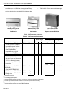
Fig. 7. Barrier configuration.
CAUTION
Equipment Damage Hazard.
Never install more than one wire per terminal unless
using factory-supplied jumper with spade terminal.
2. Firmly tighten each terminal screw.
3. Fit wires as close as possible to the subbase. Push
excess wire back into the hole.
4. Plug hole with nonflammable insulation to prevent drafts
from affecting the thermostat.
WIRES THROUGH
WALL OPENING
WALL
WALL
ANCHORS
(2)
SUBBASE
MOUNTING
SCREWS (2)
M926
MOUNTING
HOLES
SPIRIT LEVEL
M927
WIRING
TERMINAL
THERMOSTAT
CABLE OPENIN
G
TO SPRING FINGER
CONTACTS ON
THE THERMOSTAT
(UP TO 12)
MOUNTING
HOLES (4)
POST FOR
MOUNTING
THERMOSTAT (2)
F
OR STRAIGHT
I
NSERTION–
S
TRIP 5/16 IN. (8 MM)
FOR WRAPAROUND–
STRIP 7/16 IN. (11 MM
)
SUBBASE TERMINAL SCREW
M928
BARRIER