


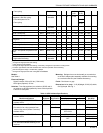
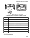
T874 MULTISTAGE THERMOSTATS AND Q674 SUBBASES
7 60-2485—8
MERCURY NOTICE
This control contains mercury in a sealed tube. Do not
place control in the trash at the end of its useful life.
If this control is replacing a control that contains
mercury in a sealed tube, do not place your old control
in the trash.
Contact your local waste management authority for
instructions regarding recycling and the proper
disposal of this control, or of an old control containing
mercury in a sealed tube. If you have questions, call
the Honeywell Customer Response Center at
1-800-468-1502.
INSTALLATION
When Installing this Product…
1. Read these instructions carefully. Failure to follow them
could damage the product or cause a hazardous condi-
tion.
2. Check the ratings given on the product to make sure the
product is suitable for your application.
3. Installer must be a trained, experienced service techni-
cian.
4. After installation is complete, check out product opera-
tion as provided in these instructions.
CAUTION
Hazardous Voltage.
Can damage heating/cooling system.
1. Disconnect power supply before beginning instal-
lation to prevent electrical shock or equipment
damage.
2. Do not short across coil terminals on relay. This
can burn out thermostat heat anticipator.
3. To prevent interference with the thermostat link-
age, keep wire length to a minimum and run wires
as close as possible to the subbase.
4. Do not overtighten thermostat captive mounting
screws because damage to subbase threads can
result.
IMPORTANT
An incorrectly leveled thermostat will cause the tem-
perature control to deviate from setpoint. It is not a
calibration problem.
Location
Install the thermostat about 5 ft (1.5m) above the floor in an
area with good air circulation at average temperature.
Do not mount the thermostat where it can be affected by:
— drafts or dead spots behind doors, in corners or under
cabinets.
— hot or cold air from ducts.
— radiant heat from the sun, fireplace, or appliances.
— concealed pipes and chimneys.
— unheated (uncooled) areas such as an outside wall behind
the thermostat.
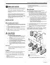
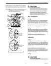
Mount Subbase
The subbase can be mounted on a vertical outlet box,
horizontal outlet box or directly on the wall.
1. If the subbase is mounted on a vertical outlet box, order
Honeywell part no. 193121A Adapter Assembly. See
Fig. 4. The assembly includes an adapter ring, two
screws and a cover plate to cover marks on the wall.
Install the ring and cover plate on the vertical outlet box.
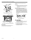
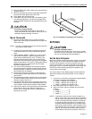
NOTE: For a wall installation, hold subbase in position and
mark holes for anchors. See Fig. 5. Wall anchors
must be obtained from local hardware store. Be care-
ful that the wires do not fall back into the wall open-
ing. Set aside subbase. Drill four
3/16 in. (4.8 mm) holes and gently tap anchors into
the holes until flush with the wall.
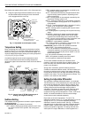
2. Pull wires through the cover plate (if used) and subbase
cable opening. See Fig. 6.
3. Secure the cover plate (if used) and subbase with the
screws provided. Do not fully tighten the subbase
screws.
Level the subbase using a spirit level, see Fig. 7, and firmly
tighten subbase mounting screws. The subbase mounting
holes provide for minor out-of-level adjustments.
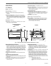
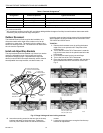
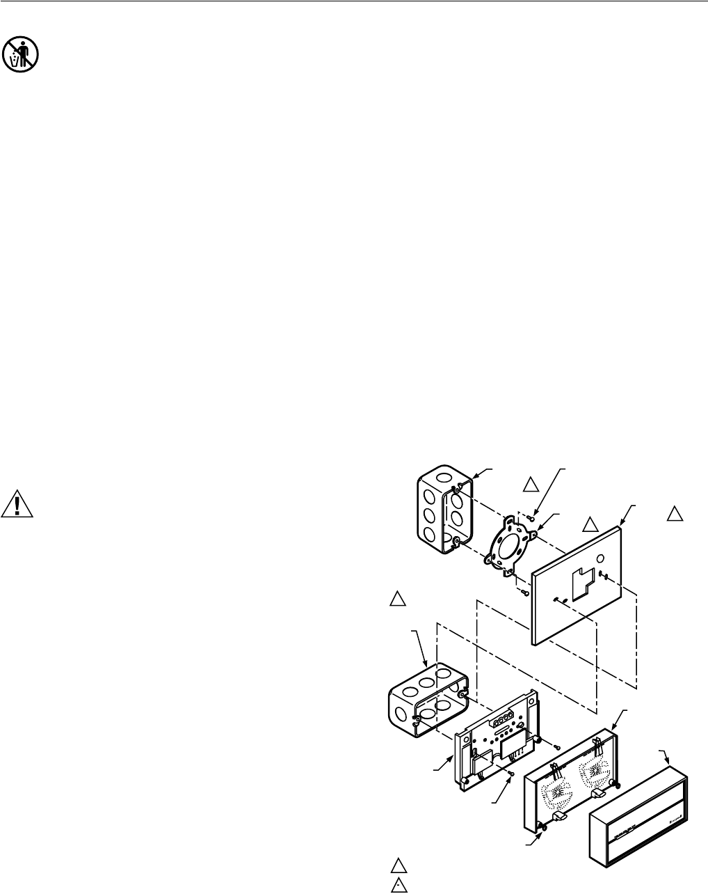
Fig. 4. Installing Q674 Subbase on outlet box.
M6009
VERTICAL
OUTLET
BOX
ADAPTER
RING
COVER
PLATE
MOUNTING
SCREWS (2)
1
SUBBASE
SUBBASE
MOUNTING SCREWS (2)
HORIZONTAL
OUTLET
BOX
1
2
2
1 NOT INCLUDED WITH UNIT.
2 ACCESSORY PART AVAILABLE (193121A).
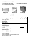
THERMOSTA
T
CAPTIVE
MOUNTING SCREWS (2)
50 60 70 80
50 60 70 80
HEAT
COOL
THERMOSTAT
COVER
50 60 70 80