


T8700B,C AN ELECTRONIC ROUND PROGRAMMABLE THERMOSTAT
68-0197—1
9
OPERATION
Zero Droop Performance
The T8700 Thermostat can control temperature closer to
setpoint than electromechanical thermostats. This is because
proportional plus integral control (P + I) maintains a constant
indoor temperature independent of the outdoor temperature.
This feature allows the T8700 Thermostat to provide tight
temperature control with virtually no noticeable swings in
temperature, a condition referred to as
droop
. This zero droop
performance provides improved comfort and occupants do not
need to continually adjust thermostat settings to be
comfortable, even during extreme weather.
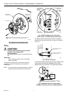
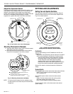
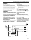
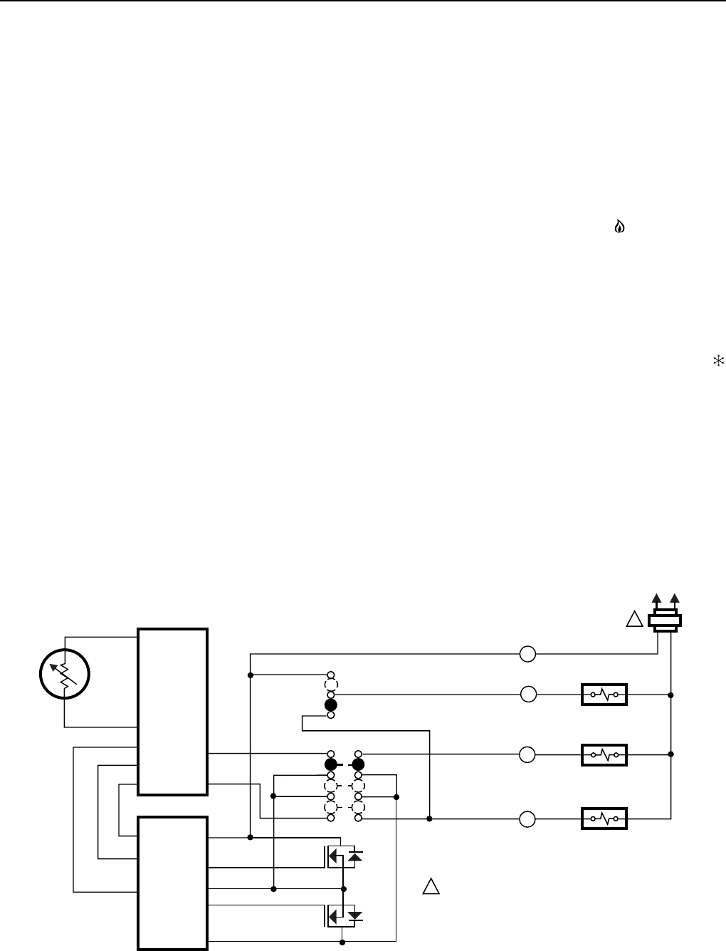
Power Stealing
The T8700 Thermostat steals power through the heating and/or
cooling system controls; therefore, it can be used in applications
where it is not possible to run additional wires. See Fig. 15.
The T8700 Thermostat requires only 2.5 mA of load current
when the heating and/or cooling is on. When the heating and/or
cooling is off, the thermostat operates at 0.1 mA. This low
current draw allows the T8700C to be used with most 24V
heating and/or cooling systems.
The T8700 Thermostat operates only when mounted on the
wallplate with 24V applied. Batteries are not required for
operation. Temperature setpoints, programming and
configuration settings are retained permanently in memory.
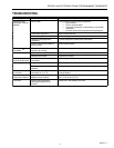
Sequence of Operations
The Heat and Cool outputs are transistor controlled. A loss of ac
power or a change in the System switch setting can turn off
outputs. Table 5 shows the Fan and System sequence of
operations.
Fan Control
The FAN switch settings for the T8700B1015 with Fan and
T8700C are ON and AUTO.
ON: The fan runs continuously.
AUTO: In cooling, the fan starts and stops with the cooling
equipment. In heating, the fan starts a few minutes after
the heating equipment turns on. With the Fuel switch in
the E position for electric heat, the fan starts and stops
with the heating equipment.
Heat Mode
With the T8700 system switch in the HEAT position, the
thermostat controls the heating system. On a call for heat, the
W terminal is energized and a flame icon shows on the
digital display.
If the Fuel switch is in the E position, both the W and G
terminals are energized on a call for heat.
Cool Mode
With the T8700C System switch in the Cool position, the
thermostat controls the cooling system. On a call for cool,
the G and Y terminals are energized and a snowflake icon
shows on the digital display. A flashing snowflake indicates
that the minimum-off timer is in effect.
Minimum Off-Timer T8700C
A minimum off-timer for the T8700C assures that the cooling
compressor does not come on again for at least five minutes
after it turns off. The minimum-off timer is triggered when the
compressor turns off or when the System switch is changed.
If the compressor turns off when the setpoint is changed, the
minimum-off timer is triggered. Power interruption and power
restoration also trigger the minimum off-timer.
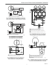
Fig. 15. T8700C power stealing internal schematic.
L1
(HOT)
L2
1
1
POWER SUPPLY. PROVIDE DISCONNECT MEANS AND
OVERLOAD PROTECTION AS REQUIRED.
SYSTEM SWITCH
FAN SWITCH
AUTO
ON
OFF
HEAT
COOL
Y
W
G
R
FAN RELAY
COOL RELAY
HEAT RELAY
POWER
SUPPLY
LOGIC AND
CONTROL
THERMOSTAT
LOGIC
THERMISTOR
SENSOR
M10360
MOSFET
MOSFET