


T8700B,C AN ELECTRONIC ROUND™ PROGRAMMABLE THERMOSTAT
68-0197—1
6
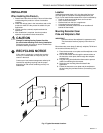
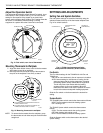
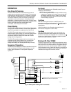
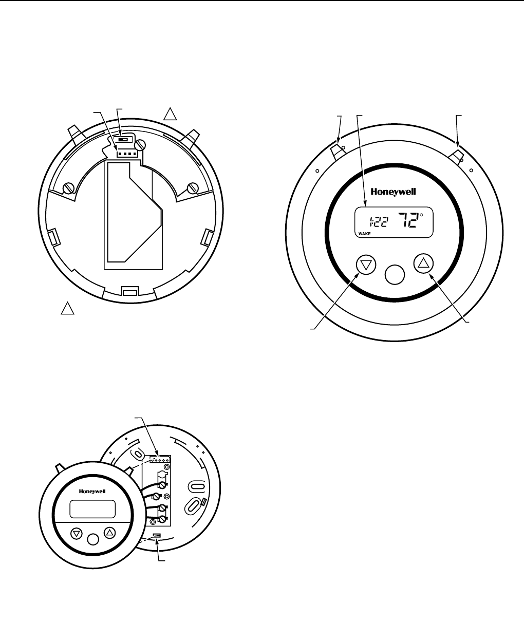
Adjust Fan Operation Switch
The thermostat fan operation switch, labeled Fuel switch, is set
at the factory in the F position. See Fig. 12. This is the correct
setting for most systems. If this system is an electric heat
system, set the switch to the E position. The E setting allows the
fan to turn on immediately with the heating or cooling
equipment in a system where the G terminal is connected.
Fig. 12. Fuel switch, rear view of thermostat.
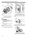
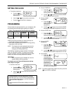
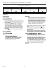
Mounting Thermostat to Wallplate
1. Align and attach bottom center notch on the thermostat
with bottom center tab on wallplate.
2. Next align tabs and connector at top of thermostat to
the pins on the wallplate. Press firmly to attach.
Fig. 13. Mounting thermostat to wallplate.
NOTE: To remove the thermostat from the wallplate, grasp
the thermostat on both sides and pull the thermostat
straight out.
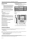
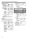
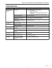
Fig. 14. T8700 time/temperature display
and System/Fan switches (T8700C shown).
Fan Switch
The Fan switch settings for the T8700B1015 with Fan and
T8700C are:
ON: The fan runs continuously. Use to improve air circulation.
AUTO: Normal setting for most homes. In cooling, the fan
starts and stops with the cooling equipment. In heating,
the heating system directly controls the fan equipment.
The fan may start a few minutes after the heating
equipment turns on (for most systems). When the
thermostat Fuel switch is set to the E position for electric
heat, the fan starts and stops with heating equipment.
Slide the Fan switch on the thermostat to the desired fan
setting.
System Switch
The T8700B System switch controls the thermostat as follows:
HEAT: The thermostat controls the heating system.
OFF: Heating is off.
The T8700C System switch controls the thermostat as
follows:
COOL: The thermostat controls the cooling system.
OFF: Both heating and cooling are off.
HEAT: The thermostat controls the heating system.
Slide the System switch on the thermostat to the desired
system setting.
Set
M12546A
TIME/TEMPERATURE
DISPLAY
INCREASE
SETTING
DECREASE
SETTING
FAN SWITCH
(SOME MODELS)
SYSTEM SWITCH
C
O
O
L
O
F
F
H
E
A
T
F
A
N
O
N
A
U
T
O
PM
SETTINGS AND ADJUSTMENTS
Setting Fan and System Switches
Fan and system settings are controlled manually using the
switches located at the top of the thermostat wallplate. See
Fig. 14 for switch locations.
M12531A
FUEL SWITCH
F
E
1
1
T8700C AND T8700B WITH FAN ONLY.
CONNECTOR
M13208
ALIGN AND ATTACH BOTTOM CENTER NOTCHS ON
THERMOSTAT/WALLPLATE.
ALIGN PINS ON WALLPLATE WITH CONNECTOR ON
THERMOSTAT. PRESS FIRMLY TO ATTACH.
AA
C
O
O
L
O
F
F
H
E
A
T
F
A
N
O
N
A
U
T
O
BOTTOM CENTER
NOTCH
PINS
B
Set