


T8700B,C AN ELECTRONIC ROUND™ PROGRAMMABLE THERMOSTAT
68-0197—1
4
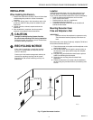
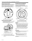
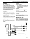
Fig. 3. Mounting decorator cover plate
and wallplate on wall (T8700C shown).
Wiring
CAUTION
Damage To Heating/Cooling System Possible.
Be careful when handling wires
during installation.
Disconnect power at furnace or at main breaker/fuse
box.
IMPORTANT
Use an 18-gauge maximum wire for wiring the
T8700 Thermostat.
All wiring must comply with local electrical codes and
ordinances. A letter is located near each terminal for
identification.
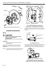
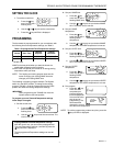
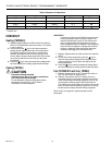
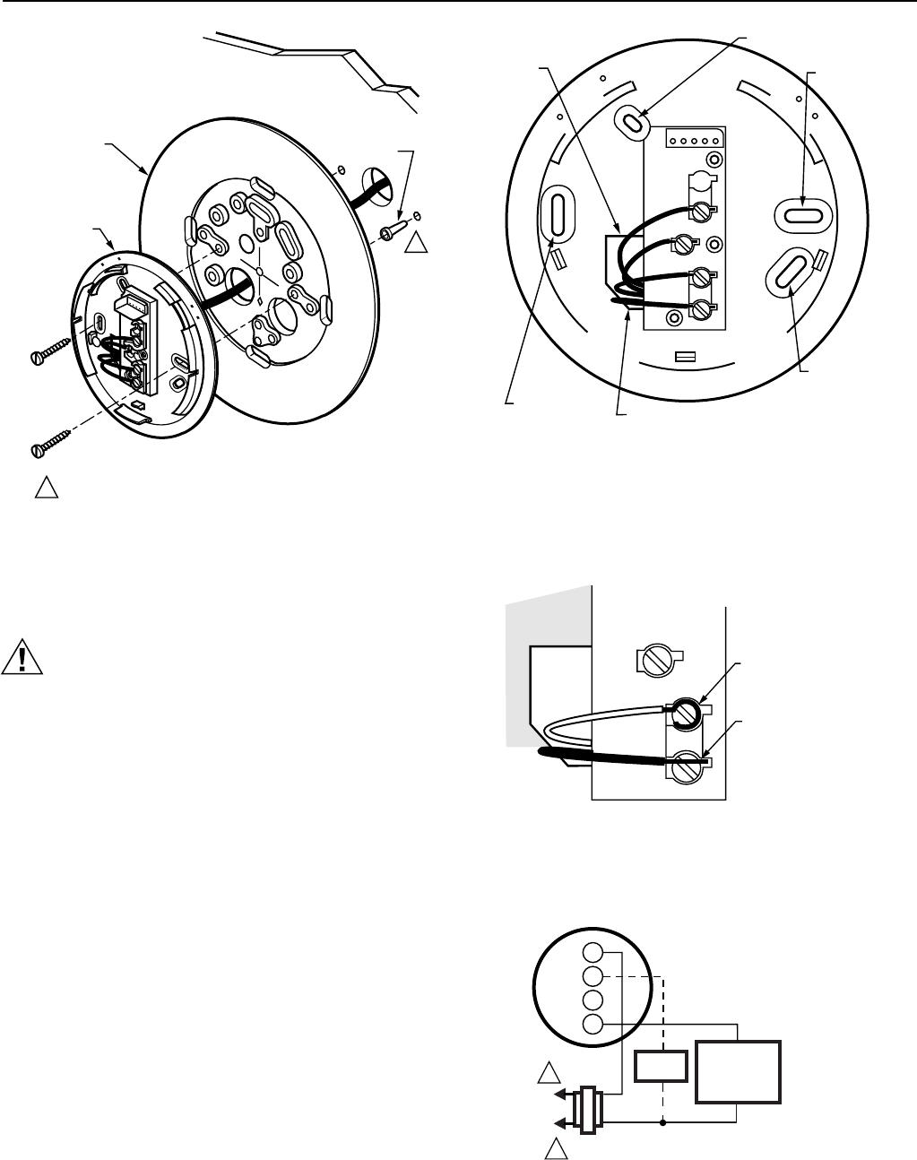
NOTE: To ensure proper mounting of thermostat, restrict all
wiring to the left side of the terminals. See Fig. 4.
Fig. 4. T8700C wallplate wiring connections.
(Refer to Table 1 for T8700B wiring connections.)
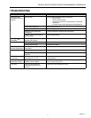
The shape of the terminals permits insertion of straight or
wraparound wiring connections; either method is acceptable.
See Fig. 5.
Fig. 5. Wiring connections.
The T8700 Thermostat steals power through the heating and/or
cooling system controls and is adaptable to most, 24 Vac
systems. Refer to Fig. 6 through 11 for typical wiring hookups.
M12529
ALTERNATE
MOUNTING
SCREW HOLE
MOUNTING
SCREW
HOLE
MOUNTING
SCREW HOLE
ROUTE WIRING AS
SHOWN THROUGH
ENTRANCE
HOLE
WIRING ENTRANCE HOLE
ALTERNATE MOUNTING
SCREW HOLE
W
Y
G
R
C
O
O
L
O
F
F
H
E
A
T
F
A
N
O
N
A
U
T
O
M12537
FOR WRAPAROUND, STRIP
7/16 IN. (11 mm)
FOR STRAIGHT INSERTION,
STRIP 5/16 IN. (8 mm)
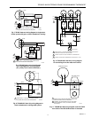
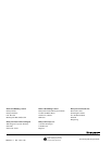
Fig. 6. T8700B1007 Heat Only wiring diagram
T8700B1015 Heat Only with Fan includes dotted line.
M12532A
DECORATOR
COVER PLATE
WALL
WALLPLATE
PLASTIC SCREW
ANCHOR (2)
C
O
O
L
O
F
F
H
E
A
T
F
A
N
O
N
A
U
T
O
1
1
WHEN USING WALL ANCHORS, DRILL 3/16 INCH HOLES FOR
DRYWALL, 7/32 INCH HOLES FOR PLASTER OR WOOD.
L1
(HOT)
L2
1
1
W
R
HEATING
PRIMARY
CONTROL
24V
POWER SUPPLY. PROVIDE DISCONNECT MEANS AND
OVERLOAD PROTECTION AS REQUIRED.
M16005B
T8700B
FAN
RELAY
G