


6
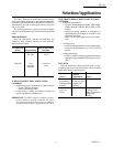
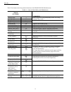
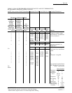
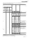
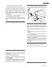
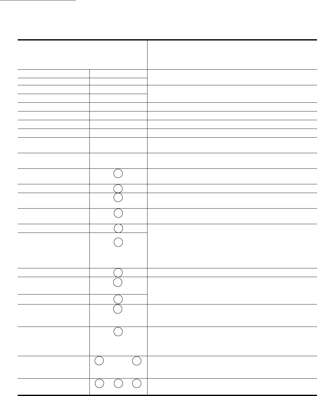
Table 2 lists features and wiring terminal functions of the TRADELINE T8611M thermostat.
TABLE 2—T8611M FEATURES AND TERMINALS.
T8611M
FEATURES
COMMENTS
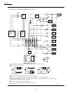
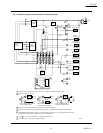
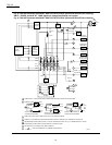
Heating Stages 3 May be applied to 2-stage heat pump systems; see wiring
Cooling Stages 2 diagrams Figs. 6 and 7.
Changeover Auto
Programming 7-day
SYSTEM LED Yes Lights on call for heat or cool.
EM. HEAT LED (red) Yes Lights continuously in EM. HEAT mode.
AUX. HEAT LED (green) Yes Lights during call for final auxiliary heat stage.
CHECK LED (yellow) Yes Field wired option; indicates equipment malfunction.
Remote Temperature Yes Available on T8611M7040 only. (202905A Remote Sensor
Sensing included).
WIRING TERMINAL
FUNCTION
24 Vac Common C Must be connected to control transformer to operate
thermostat.
24 Vac Power R
Compressor, Stage 1 Y
heat and cool.
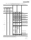
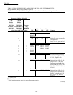
Compressor,
Y2
If applying T8611M to 1-stage cooling system, leave Y2
Stage 2 cool unconnected.
Second Stage Heat
W2
If applying T8611M to 2-stage heat systems in which the
Auxiliary (Resistive) second stage is compressorized, connect stage 2 to W2;
Third Stage Heat
W3
leave W3 unconnected.
If 2-stage heat system in which the second stage is auxillary
(electric resistive), connect auxiliary stage to W3; leave
W2 unconnected.
Fan G
Changeover Heat Mode B O/B changeover terminals are energized continuously
following first call for cool or heat, respectively.
Changeover Cool Mode O
System Monitor, L Energizes EM. HEAT LED when externally powered.
continuously energized
in EM. HEAT mode.
Emergency Heat E
energized on call for
stage 1 heat in
EM. HEAT mode
Check LED terminals
X1 X2
See wiring diagrams for hookup alternatives.
to indicate equipment
malfunction
Remote Temperature
S1 S2 S3
Available on T8611M7040 only. Must be connected to
Sensing 202905A Remote Sensor for proper thermostat operation.
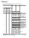
T8611M
SELECTION/APPLICATION