13 68-0076—1
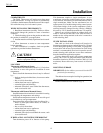
Fig. 4—Removing thermostat from subbase.
The subbase mounts directly onto the wall with the
screws and anchors included. Instead, the subbase can be
mounted on a vertical or horizontal outlet box. If you must
mount the subbase on a vertical outlet box, order 193121A
Adapter Assembly. The assembly includes an adapter
ring, two screws and a cover plate to cover marks on the
wall. Install the ring and cover plate on the vertical outlet
box as instructed.
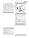
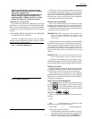
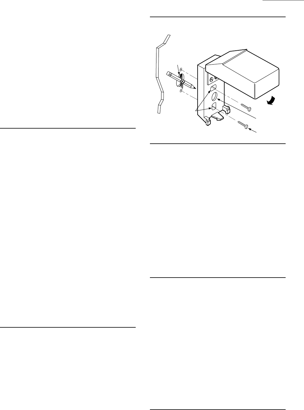
Use the subbase as a template, and with a pencil, mark
the two mounting screw positions (Fig. 5).
If drywall construction, plastic anchors must be used;
use 3/16 in. bit to drill holes for anchors. Gently tap
anchors into holes until they are flush with the wall
surface.
Thread wires through the center opening of the sub-
base.
Use a 3/16 in. bit to drill the required holes. Gently tap
anchors into holes until they are flush with the wall
surface. Thread wires through the opening in the base.
Mount remote sensor base using the screws provided. See
Fig. 6. Make sure base looks level before tightening
screws.
Fig. 6—Mounting remote sensor base on wall.
WIRING
All wiring must comply with local electrical codes and
ordinances.
Disconnect power before wiring to prevent electrical
shock or equipment damage.
The shape of the terminal barrier permits insertion of
straight or conventional wraparound wiring connections.
Either method is acceptable.
Push excess wire back into the hole, and plug hole with
nonhardening caulk, putty or insulation to prevent drafts
from affecting operation of thermostat and remote sensor,
if applicable.
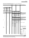
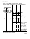
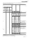
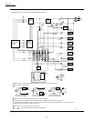
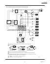
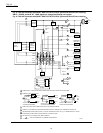
Refer to Figs. 8-10 for typical hookups of subbase and
thermostat.
After wiring remote sensor, replace cover.
NOTE: Restrict all wiring to recessed area surrounding
Mount the subbase using two screws provided. Gently
tighten screws, level top surface of subbase, and securely
tighten screws.
Fig. 5—Mounting subbase on wall.
MOUNTING REMOTE TEMPERATURE SENSOR
(IF APPLICABLE)
The remote sensor mounts directly on the wall with
screws and anchors included. Remove cover from remote
sensor (Fig. 6). Use the remote sensor base as a template,
and with a pencil, mark holes for mounting screws.
T8611M
INSTALLATION
REMOTE SENSOR
COVER
REMOTE
SENSOR BASE
WALL
MOUNTING HOLES
WIRING
HOLE
M1549B
WALL
ANCHORS (2)
MOUNTING
SCREWS (2)
WIRES
THROUGH
WALL
OPENING


