


T8611G CHRONOTHERM
®
IV DELUXE PROGRAMMABLE HEAT PUMP THERMOSTATS
69-1406—1 2
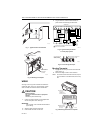
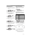
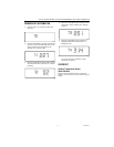
Fig. 1. Typical location of thermostat.
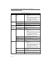
Fig. 2. Mounting the wallplate.
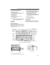
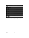
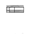
WIRING
All wiring must comply with local electrical codes and
ordinances. Refer to Fig. 3 for typical hookup. A letter
code is located near each terminal for identification.
CAUTION
Electrical Hazard.
Can cause electrical shock or equipment
damage.
Disconnect power before wiring.
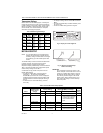
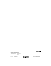
1. Loosen the terminal screws on the wallplate and
connect the system wires. See Fig. 4.
IMPORTANT
Use 18 gauge, color-coded thermostat cable for
proper wiring.
2. Securely tighten each terminal screw.
3. Push excess wire back into the hole.
4. Plug the hole with nonflammable insulation to
prevent drafts from affecting the thermostat.
Fig. 3. Typical hookup of T8611G
in a heat pump system.
Fig. 4. Correct wiring technique.
Mounting Thermostat
1. Engage tabs at the top of the thermostat and wall-
plate. See Fig. 5.
2. Press lower edge of case to close and latch.
NOTE: To remove the thermostat from the wall, first pull
out at the bottom of the thermostat; remove top
last.
Fig. 5. Mounting thermostat on wallplate.
5 FEET
[1.5 METERS]
YES
NO
NO
NO
M10106
WIRES
THROUGH WALL
WALL
MOUNTING
HOLES
M15044
MOUNTING
SCREWS
WALL
ANCHORS (2)
W2
L1
(HOT)
L2
M11311A
FAN
RELAY
Y1 G E
THERMOSTAT
C
HEAT
RELAY!
1
RW1
COMPRESSOR
CONTACTOR
EM.!HT.
RELAY
TRANSFORMER
HEAT
RELAY!
2
OT OT
OUTDOOR
SENSOR
COOLING!OR
HEATING
CHANGEOVER
VALVE
O/B
X2 LX1
EQUIPMENT
MONITOR!2
EQUIPMENT
MONITOR!1
1
POWER!SUPPLY.!PROVIDE!DISCONNECT!MEANS!AND!OVERLOAD
PROTECTION!AS!REQUIRED.
1
M4826
FOR WRAPAROUND
INSERTION STRIP
7/16 IN. (11 MM).
FOR STRAIGHT INSERTION
STRIP 5/16 IN. (8 MM).
M14628
PRESS LOWER
EDGE OF CASE
TO LATCH.
ENGAGE TABS
AT TOP OF
THERMOSTAT
AND WALLPLATE.
A.
B.