


T8600D, T8601D AND T8602D CHRONOTHERM
®
IV DELUXE PROGRAMMABLE THERMOSTATS
68-0164—1
5
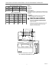
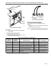
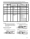
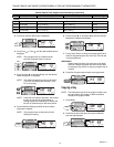
WIRES
THROUGH WALL
WALL
MOUNTING
HOLES
M15044
MOUNTING
SCREWS
WALL
ANCHORS
(2)
Fig. 3. Mounting the wallplate.
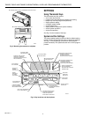
IMPORTANT
Use 18 gauge, color-coded thermostat cable for
proper wiring.
2. Securely tighten each terminal screw.
3. Push excess wire back into the hole.
4. Plug the hole with nonflammable insulation to prevent
drafts from affecting the thermostat.
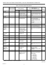
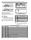
Standard
Terminal
Designations
Alternate
Terminal
Designations Typical Connection Function Terminal Type
B— Heating damper or changeover valve Output 24V powered contact
CB
a
, C, X1, X2 Common Input
GF Fan relay Output 24V powered contact
OR Cooling damper or changeover valve Output 24V powered contact
OT, OT — Outdoor temperature sensor (C7089B) Input —
RV 24V system or heating transformer Input —
RC — 24V cooling transformer Input —
W H1, R3 Heating relay Output 24V powered contact
Y C1, M Compressor contactor Output 24V powered contact
a
Some OEM models label the terminal for transformer common B.
M4826
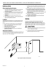
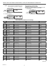
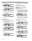
FOR WRAPAROUND
INSERTION STRIP
7/16 IN. (11 MM).
FOR STRAIGHT
INSERTION STRIP
5/16 IN. (8 MM).
Fig. 4. Proper wiring technique.
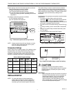
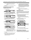
Mounting Thermostat Wallplate
The thermostat mounts on the wallplate after they are
installed.
1. Engage tabs at the top of thermostat and wallplate. See
Fig. 5.
2. Press lower edge of case to latch.
NOTE: To remove the thermostat from the wall, first pull out
at the bottom of the thermostat; then remove the top.
Table 4. Terminal Designations and Descriptions.