


T6570, T8570 SERIES DIGITAL FAN-COIL THERMOSTATS
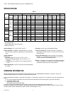
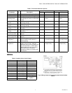
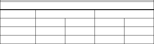
Table 4. Energy Saving Mode Default Settings
Energy Savings Mode – Setpoints
Heating Setpoint Cooling Setpoint
Description Default Range Default Range
°C Scale 18°C 10-18°C 25°C 25-30°C
°F Scale 65°F 50-65°F 77°F 77-90°F
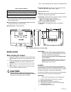
Additional Switches
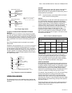
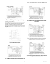
FAN SPEED SWITCH (SP3T LINE VOLTAGE)
Where supplied, the fan switch allows the selection of three
different settings: low, medium, or high.
NOTE: The installer should select Constant Fan mode if the
fan motor is a type that does not start reliably at low
speed.
SYSTEM HEAT/COOL SWITCH (SPST LOW VOLTAGE)
Where supplied, this switch signals the microprocessor to
operate the relays in either heating or cooling mode: In heating
mode, the cooling relay is disabled. In cooling mode, the
heating relay is disabled.
User Programming Modes
TEMPERATURE (COMFORT) SETPOINT
The temperature setpoint can be adjusted between 10°C and
30°C in steps of 0.5°C by using the [UP] and [DOWN] keys. If
°F is set within the installer setup mode (see later), the range
will be 50°F to 90°F, adjustable in 1°F steps.
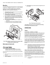
DISPLAY
The measured room temperature is normally displayed (unless
rt = 0 in the installer setup mode), and the first press of the
[UP] or [DOWN] keys will switch to display the user setpoint. If
no key is pressed for 5 seconds, the display will return to
showing the room temperature.
When the cooling relay is closed, this will be indicated by a
(snowflake) symbol, whereas closure of the heating relay will
be indicated by a (flame) symbol.
If there is a wiring problem or the room temperature is less
than 5°C (40°F) or over 38°C (100°F) the display will return a
SF (Sensor Failure) warning. If this warning is not due to a
wiring problem it will disappear once the remote sensor or
thermostat comes within the 4.5 to 37.8°C (40 to 100°F) range.
If the SF warning is due to a faulty remote sensor connection
the thermostat will not transfer measurement to the internal
sensor. To resolve the faulty connection the thermostat must
be powered down, the remote sensor connection must be
removed or fixed and then the thermostat must be re-powered.
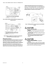
Installer Setup Mode
The thermostat allows many of its operating parameters to be
adjusted via an Installer Setup Mode. Each operating
parameter has a two-letter identifier code, which is shown on
the display during the Installer Setup Mode programming
sequence. A description of these is shown in Table 5.
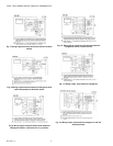
PROGRAMMING PARAMETERS
The installer setup mode is accessed by reducing the setpoint
to 10°C (50°F), waiting 3 seconds or until the room
temperature is displayed, and then pressing the [UP] and
[DOWN] keys simultaneously for 3 seconds.
If the installer setup has previously been entered and the
Minimum Cooling Setpoint increased above 10°C (50°F), the
installer setup mode is accessed by reducing the setpoint to
the new value before pressing the two buttons.
The first parameter identifier will be displayed at this point and
the parameter value can be changed by pressing the [UP] key.
The first press displays the default value and any subsequent
press alters the value. The values will wrap around.
To select the parameter value and move to the next parameter,
press [DOWN]. After the final parameter is selected, a further
press of the [DOWN] key will exit from the programming mode.
PARAMETER VALUES
Each parameter has a default value that is used when the
thermostat is first powered up. This value can be changed from
within the Installer Setup Mode, and once changed, it will be
stored in the EEPROM so it is not lost in the event of power
interruption.
If the user wishes to restore the parameters to the default
values, this can be done by changing the temperature scale tS
from °C to °F (or °F to °C) and back again.
PROGRAMMING EXAMPLE
To enter the installer setup mode:
1. Press to change the temperature setpoint to 10°C
(50°F).
2. Wait 3 seconds, or until the room temperature is dis-
played.
3. Press and hold together until [tS] is displayed.
4. Press once to show the default Temperature Scale
value. Continue to show all possible values of this
parameter in sequence.
5. When the desired value is displayed, it is selected by
pressing once. This will also move to the next parameter,
whose identifier will now be displayed.
6. Continue to use to move from one parameter to the next,
and to alter the parameter value.
7. When the last parameter [rt] has been selected, a final
press of will return the display to its normal operating
mode.
95C-10897–6 6