T6570, T8570 SERIES DIGITAL FAN-COIL THERMOSTATS
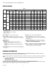
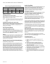
Table 2. Electrical Rating
50-60 Hz 24V 120V 208V 230V 277V
Amps (Resistive) 3.8 3.8 3.8 3.8 3.8
Full Load Inductive 3.0
3.0
1
3.0 3.0 3.0
Pilot Duty 100 VA
1
Equivalent to NEMA 1/8 horsepower rating; allowable load
must be determined by adding nameplate full load and locked
rotor rating of all loads.
Minimum Operational Life (at maximum load): Thermostat
contacts (at 120 Vac): 100,000 cycles
Manual Switches: 10,000 operations.
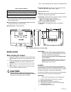
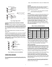
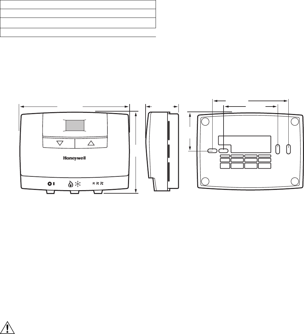
M12081A
3-11/16
(94)
4-3/16 (122)
1-7/16 (37)
1-1/2
(38)
3-5/16 (84)
2-3/8 (60)
Energy Savings Input: 24 Vdc dry contact, maximum resis-
tance of 1000 ohms. Note 'Caution', page 3.
Protection Class: IP30.
Approvals: CSA Certified C/US LR158158 for Canada and
the U.S.A. Meets CE requirements.
Accessories: Adapter plate for mounting on single- or double-
gang NEMA-standard vertical switch box:
272878 - line voltage models, 24V 2000 series
272881 - 24 V models, 1000 series
T8109 - remote temperature sensor for
T8575D W6380 - fan switching center for T8574/T8575
products
Fig. 1. Nominal dimensions in inches (mm)
INSTALLATION
When Installing this Product...
1. Read these instructions carefully. Failure to follow them
could damage the product or cause a hazardous condi-
tion.
2. Check the ratings given in the instructions and on the
product to make sure the product is suitable for your
application.
3. Installer must be a trained, experienced service techni-
cian.
4. After installation is complete, check out product opera-
tion as provided in these instructions.
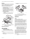
CAUTION
Electrical Shock or Equipment Damage Hazard.
Can shock individuals or short equipment circuitry.
Disconnect power supply before installation.
IMPORTANT
T6570 Series are line voltage powered devices.
All wiring must comply with national and local electri-
cal codes, ordinances and regulations.
Provide disconnect means and overload protec-
tion as required.
T8570 Series thermostats must be powered by an
Approved 24 Vac, Class 2 transformer (such as a
W6380 Relay Control Center).
Location
The T6570, T8570 series thermostats are the temperature
control element in a fan-coil or air-conditioning system. They
must be located about 1.5m (5 ft.) above the floor in a position
with good air circulation to sense room temperature.
The optional T8109 sensor can be used to sense temperature
in return air ductwork, instead of at the thermostat
IMPORTANT
Do not mount device where it can be affected by:
1. Drafts or dead spots behind doors or in corners.
2. Hot or cold air from ducts.
3. Radiant heat from the sun or appliances.
4. Unheated (uncooled) areas such as an outside wall
behind the thermostat.
5. Concealed pipes or chimneys.
3 95C-10897–6


