


T6570, T8570 SERIES DIGITAL FAN-COIL THERMOSTATS
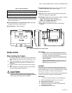
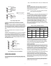
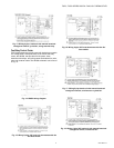
SINGLE STAGE COOLING
C
23.0
PROPORTIONAL
22.5
BAND
22.0
21.5
21.0
USER
20.5
SETPOINT
20.0
1
1 USER SETPOINT CHANGED
TO 21.5 C (71 F) FROM
SINGLE STAGE HEATING
C
1
23 C (73 F) OR 20 C (68 F).
23.0
22.5
USER
SETPOINT
22.0
21.5
21.0
PROPORTIONAL
BAND
20.5
20.0
M17477
Fig. 4. Single stage control.
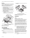
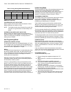
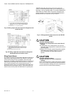
AUTOMATIC CHANGEOVER WITH ZERO ENERGY DEADBAND
(SEE FIG. 5)
This type of control is available on auto-changeover models
only. The user setpoint centers on the Zero Energy Deadband.
The cooling switch-off-point is positioned at the bottom end of
the cooling proportional band. Likewise, the heating switch-off
point is positioned at the top end of the heating proportional
band.
Zero Energy Deadband width is selectable in the Installer
Setup mode.
EXAMPLE: Using a deadband of 2°C (4°F) and a user setpoint
of 22°C (72°F), the effective heating setpoint is 21°C (70°F)
and the effective cooling setpoint is 23°C (74°F). A change to
the user setpoint causes both heating and cooling setpoints to
change in parallel. This change is restricted to the minimum
cooling setpoint or maximum heating setpoint limits set within
the Installer Setup mode.
C
COOLING
25.5
PROPORTIONAL
25.0
BAND
24.5
24.0
DEADBAND
1
1
USER
23.5
SETPOINT
23.0
22.5
HEATING
22.0
PROPORTIONAL
21.5
BAND
21.0
20.5
20.0
USER SETPOINT CHANGED FROM
22 C (72 F) TO 23.5 C (74 F).
M17478
Fig. 5. Sequence control with deadband.
OPERATING MODES
The thermostat has two main operating modes: Comfort and
Energy Savings. It also has an OFF mode selected by the On/
Off switch.
OFF MODE
When the system switch is set to Off, power is removed from
the thermostat electronics and output terminals, and the
display will go blank. The thermostat will reboot when power is
restored with the On/Off switch.
NOTE: This On/Off switch is a functional switch and should
not be used as an isolating switch.
STARTUP
On first powering up, or after the On/Off switch has been set to
On, the thermostat undergoes a startup and self-checking
sequence: First, all LCD display segments are illuminated to
check the display. Next a number appears to indicate the
software version. The final check is a check of the sensor. On
completion of the startup sequence, after approximately 2
seconds, the thermostat will resume normal control in either
Comfort or Economy mode. On initial power on, the
temperature setpoint defaults are as shown in the following
table. The current setpoint is stored in EEPROM, and if the
thermostat is switched off, then on again, it will resume control
at the last known setpoint.
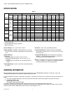
Table 3. Power Up Default Setpoints
Power Up Default Setpoints
1 relay or heat cool changeover
models
2 relay + cool
sequence models
°C Scale °F Scale °C Scale °F Scale
Setpoint
Default
22 73 22 73
Cooling OFF
point
– – 23 75
Heating OFF
point
– – 21 71
COMFORT MODE
This is the normal operating mode where the thermostat
controls to the setpoint selected by the user. On initial power
up, the user setpoint will return to the last known or default
value. Control action will be determined by either the default
settings or the installer-set parameters. (See page 6)
ENERGY SAVINGS MODE
Energy Savings mode is activated by a dry contact closure on
the special Energy Management System (EMS) input from an
occupancy detector, window contact, etc. If the signal via input
terminals 10 and 11 is calling for Energy Savings mode, then
the thermostat will control to user/installer defined setback
setpoints for increased energy savings. The display will show a
$ symbol to indicate the Energy Savings mode is active.
For example, if the user setpoint is 21°C (70°F) and the Energy
Savings mode setpoint for cooling (unoccupied cooling
setpoint) has been set to 28°C (82°F), then the thermostat
controls to 28°C (82°F) when the input signal activates the
economy mode. There is no user override as long as the EMS
signal is present. The default Energy Savings mode setpoints
are shown in table 4.
The Energy Savings mode input can be configured within the
installer setup mode to be activated by either a short-circuit
(default) or open-circuit signal.
5 95C-10897–6