


40007507-001
T6570, T8570 SERIES DIGITAL FAN-COIL THERMOSTATS
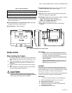
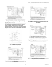
Mounting
Any T6570, T8570 series thermostat can be mounted directly
on the wall on a 65x65mm junction box, or a 2"x4" horizontal
junction box. An optional adapter plate is available for
mounting on a 4"x4" or vertical junction box. (See Fig. 2)
Mounting screws are supplied for alternatives.
1. Feed leadwires through wiring access hole of wallplate
and adaptor plate (if used).
2. Attach supply wires using wire nuts (not provided), or
screw terminals, as appropriate.
3. Locate wallplate in the horizontal mounting position. See
Fig. 2 if using the vertical junction box adapter plate.
4. Push leadwires into electrical junction box and attach
wallplate to box using machine screws provided in the
appropriate mounting holes.
5. Attach thermostat to wallplate:
a. Locate the two center side holes on the back of the
thermostat.
b. Align the holes with the two wallplate side tabs.
c. Press down firmly to snap thermostat into place.
M17505
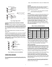
Fig. 2. Mounting the vertical junction box adapter plate
M17505 Optional adapter plate.
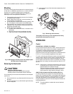
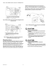
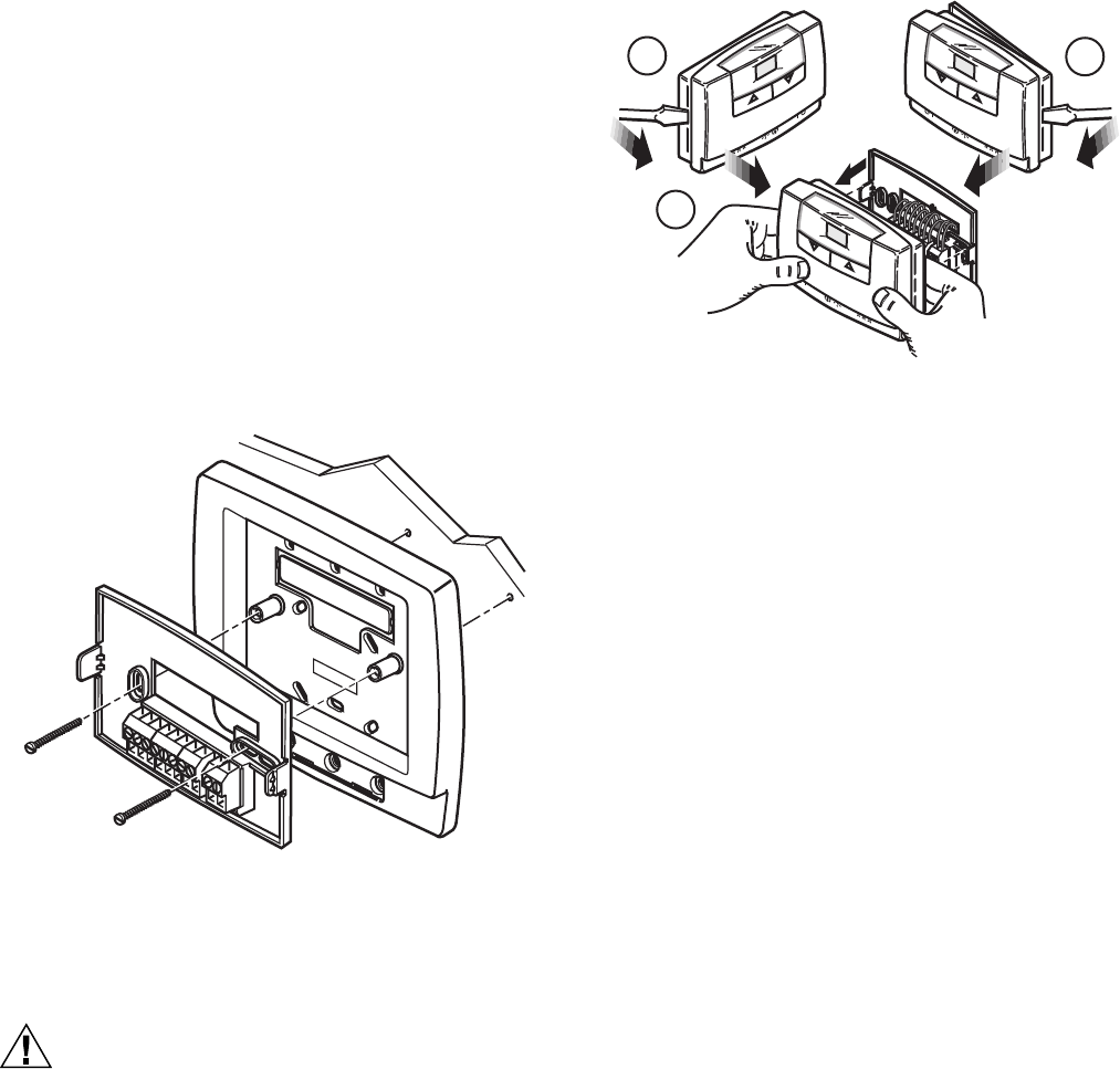
Removing the thermostat
CAUTION
Equipment Damage Hazard.
Improper removal can damage the thermostat.
Carefully follow the thermostat removal directions.
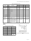
If it is necessary to remove the thermostat from the wallplate
(see Fig. 3):
1. Use a screwdriver to pry thermostat left side away from
the base.
2. Use the screwdriver to pry thermostat's right side away
from the wallplate.
3. Use both hands to pull the thermostat straight away from
the wallplate.
1
2
3
M15396
Fig. 3. Removing the thermostat
Thoroughly check wiring to the wallplate before finally
mounting the thermostat on the wall.
OPERATION
Control
PROPORTIONAL + INTEGRAL (P+I) CONTROL
Like a mechanical thermostat, the T6570, T8570 Series have
On/Off control output. However, this output is regulated by a
P+I algorithm, enabling the thermostat to control closer to
setpoint than conventional thermostats. This results in
performance where the space temperature is maintained within
0.75°C (1.5°F) of the setpoint regardless of fan speed.
P+I action minimizes the difference between the temperature
setpoint and the effective control point by adjusting the output
on-time until the control point matches the setpoint. The on-
time is based on a fixed cycle rate of 4 cycles/hour for cooling
(8 cycles/hour for heating), and the proportional band is 1.6°C
(2.9°F).
NOTE: Integral action corrects the temperature control errors
of proportional-only control, but it is slower to react to
large temperature or setpoint changes.
These thermostats also feature optional built-in time
delays for equipment protection which can inhibit
rapid response to large setpoint changes if active.
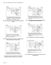
SINGLE-STAGE COOLING OR HEATING CONTROL (SEE FIG. 4)
In cooling mode the user setpoint will be positioned at the
bottom of the Proportional Band, so the setpoint will effectively
be the temperature where the cooling switches off. In heating
mode the user setpoint will be positioned at the top of the
Proportional Band, and this will be the temperature where the
heating switches off.
NOTE: This also applies to models with manual heat/cool
changeover.
95C-10897–6 4