


T7351 COMMERCIAL PROGRAMMABLE THERMOSTAT
63-2666—02 4
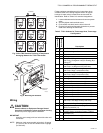
CAUTION
Equipment Damage Hazard.
Can damage the TIM connection beyond repair.
Disconnect the TIM cable prior to opening or closing
the thermostat cover.
NOTE: Allow sufficient clearance below the thermostat to
plug in the TIM cable.
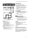
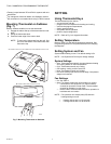
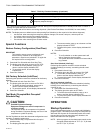
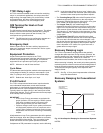
Install the remote-mounted sensor(s) about 5 ft. (1.5 m) above
the floor in an area with good air circulation at average
temperature. (See Fig. 2.)
NOTE: Only TR21 models with neither setpoint adjustment
nor bypass can be used for temperature averaging.
Fig. 2. Typical Location of Thermostat or Remote-Mounted
Sensor.
IMPORTANT
To avoid electrical interference, which can cause
erratic performances, keep wiring runs as short as
possible and do not run thermostat wires adjacent to
the line voltage electrical distribution systems. Use
shielded cable (Belden type 8762 or equivalent for
2-wire). The cable shield must be grounded only at
the controlled equipment case.
Mounting Subbase
The subbase mounts horizontally or vertically.
IMPORTANT
• When using the internal temperature sensor, the
device must be mounted horizontally (with the LCD
facing upwards). Precise leveling is not needed.
• When using remote sensors, thermostat mounting
orientation does not matter.
Wall mounting (using standard drywall screws) is standard.
Mounting to a 2 in.(50.8 mm) by 4 in. (101.6 mm) wiring box
can be accomplished:
— for a horizontal box, no extra hardware is required.
— for a vertical box, part 209651A is required.
— Mount to European standard wall box 2.4 in. (having 61 mm
between mounting screws in a horizontal line) with or
without adaptive hardware.
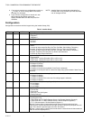
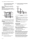
1. Position and level the subbase.
NOTE: A level wallplate is only for appearance. The
thermostat functions properly when not level.
2. Use a pencil to mark the mounting holes.
(Refer to Fig. 6.)
3. Remove the subbase from the wall and drill two 3/16 in.
(4.76 mm) holes in the wall (if drywall) as marked. For
firmer material such as plaster or wood, drill two 7/32 in.
(5.56 mm) holes.
4. Gently tap anchors (provided) into the drilled holes until
flush with the wall.
5. Position the subbase over the holes, pulling wires
through the wiring opening.
6. Loosely insert the mounting screws into the holes.
7. Tighten mounting screws.
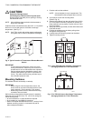
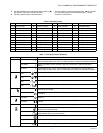
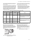
Fig. 3. Four TR21 Sensors providing a Temperature
Averaging Network for T7351 Thermostat.
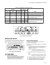
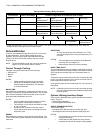
Fig. 4. Two TR21-A Sensors Providing a Temperature
Averaging Network for T7351 Thermostat.
5 FEET
(1.5 METERS)
YES
NO
NO
NO
M4823A
M29184
T4 T3
TT
SUBBASE
TR21
TT
TR21
TT
TR21
TT
TR21
M29256
T4 T3
T7350 SUBBASE
TR21-A
T4 T3
TR21-A
T4 T3
1
1 1
THE TR21-A IS A 10K OHM SENSOR.