T7351 COMMERCIAL PROGRAMMABLE THERMOSTAT
3 63-2666—02
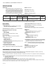
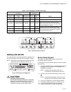
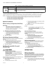
Table 2. Default Setpoints.
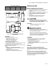
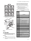
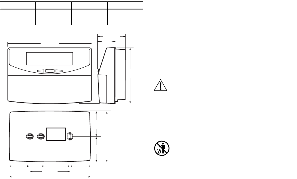
Fig. 1. Thermostat and Subbase Dimensions
in inches (mm).
Accessories:
Duct Discharge Air Sensors:
C7041B (6 or 12 in. [152 or 305 mm]),
C7041C (18 in. [457 mm]),
C7041J (12 ft. [3.66 m] averaging),
C7770A (8 in. [203 mm] probe).
Outdoor Air Sensors: C7089A, C7170A,
C7031G2014 (weatherproof).
Temperature Sensors (Remote): C7772A, TR21, TR22, TR23,
and TR24 series, TR21-WK, TR23-WK, T7771.
Economizer Logic Modules: W7210, W7212, W7215, W7459.
Humidity Sensors: H7625, H7635.
Others:
209541B FTT network termination module.
209651A Vertical Mounting Hardware Wallplate Adapter
(Trident white).
50000452-001 Troubleshooting Cable.
TG512 Universal Versaguard Thermostat guards.
INSTALLATION
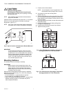
When Installing this Product...
1. Read these instructions carefully. Failure to follow them
could damage the product or cause a hazardous
condition.
2. Check ratings given in instructions and on the product to
ensure the product is suitable for your application.
3. Installer must be a trained, experienced service
technician.
4. After installation is complete, check out product
operation as provided in these instructions.
CAUTION
Electrical Shock or Equipment Damage Hazard.
Can shock individuals or short equipment circuitry.
Disconnect power supply before installation.
IMPORTANT
All wiring must agree with applicable codes,
ordinances and regulations.
MERCURY NOTICE
If this control is replacing a control that contains
mercury in a sealed tube, do not place your old control
in the trash. Dispose of properly.
Contact your local waste management authority for
instructions regarding recycling and the proper disposal
of an old control. If you have questions, call Honeywell
Customer Care Center at 1-800-468-1502.
Location
Do not install the thermostat where it can be affected by:
— drafts, or dead spots behind doors and in corners.
— hot or cold air from ducts.
— radiant heat from sun or appliances.
— concealed pipes and chimneys.
— unheated (uncooled) areas such as an outside wall behind
the thermostat.
Subbase
WHEN USED TO SENSE ROOM TEMPERATURE
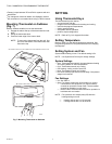
Install the thermostat about 5 ft. (1.5 m) above the floor in an
area with good air circulation at average temperature. (Refer to
Fig. 3.)
WHEN NOT USED TO SENSE ROOM TEMPERATURE
When using the remote-mounted temperature (and humidity)
sensor(s) to sense ambient conditions, install the thermostat in
an area that is accessible for setting and adjusting the
temperature and settings.
Control Occupied Not Occupied Standby
Heating 70° F (21° C) 55° F (13° C) 67° F (19° C)
Cooling 75° F (24° C) 85° F (29° C) 78° F (26° C)
6-3/4 (171)
2-3/16 (56)
1-9/16
(40)
4-1/2
(114)
2-1/32
(52)
2-1/32
(52)
4-1/16
(104)
1-5/8
(42)
2-3/8 (60)
3-1/4 (83)
6-9/16 (166)
M22432
1-5/8
(42)
SUBBASE


