


We recommend mounting the module with the terminals
down to protect them from dripping water and dust. It can
also be mounted with the terminals on either side. DO NOT
MOUNT with terminals pointing up. Fasten securely with
four No. 6-32 machine or No. 8 sheetmetal screws.
MOUNT THE SYSTEM CONTROLS
Mount any required controls, such as the gas control,
spark igniter, flame sensor, thermostat, limit and trans-
former according to manufacturer’s instructions.
WIRE THE SYSTEM
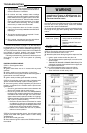
CAUTION
1. Check the wiring diagram furnished by the appli-
ance manufacturer, if available, for circuits differ-
ing from the wiring hookups shown. Carefully
follow any special instructions affecting the gen-
eral procedures outlined below.
2. Disconnect the power supply before making wir-
ing connections to prevent electrical shock or
equipment damage.
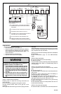
IMPORTANT
1. As shown in the wiring diagrams, a common
ground is required on:
a. The pilot burner mounting bracket, and
b. The GND(BURNER) terminal on the ignition
module. Failure to use the GND(BURNER) termi-
nal may result in intermittent loss of spark and/or
loss of flame current sensitivity.
2. Make sure the transformer has adequate VA. The
ignition module requires at least 0.2 A at 24 Vac.
Add the current draws of all other devices in the
control circuit, including the pilot and main valves
in the gas control, and multiply by 24 to determine
the total VA requirement of these components.
Add this total to 4.8 VA (for the ignition module).
The result is the minimum transformer VA rating.
Use a Class II transformer if replacement is re-
quired.
3 69-0463
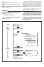
Connect Ignition Cable
Use Honeywell ignition cable or construct an ignition
cable that conforms to suitable national standards such as
Underwriters Laboratories Inc. See Tables 2 and 3.
Cable must be no longer than 36 in. [0.9 m]. To construct
a cable, fit one end of ignition cable with 1/4 in. diameter
Rajah connector receptacle and the other with a 1/4 in.
female quick connect. Protect both ends with insulated
boots.
NOTE: The cable must not run in continuous contact with a
metal surface or spark voltage will be greatly reduced.
Use ceramic or plastic standoff insulators as required.
To install:
1.Connect one end of the cable to the male quick
connect SPARK terminal on the ignition module.
2.Connect the other end of the cable to the igniter or
igniter-sensor stud on the pilot burner/igniter-sensor.
Connect Vent Damper
The D80B Vent Damper can be used with all ignition
modules, although the Molex plug provided on some mod-
ules simplifies wiring connections when used with the D80D
Plug-In Vent Damper.
Once a module with vent damper
plug has powered a vent damper circuit, it cannot be used
in a gas system without a vent damper
. A non-replaceable
fuse in the module blows on initial power-up. Once this fuse
has blown the module won’t work unless the vent damper
is connected.
To connect the plug-in model to D80D:
1. Remove the plug from the terminal strip on the ignition
module case and discard.
2. Using the wiring harness supplied, insert the matching
pin plug into receptacle on case and other end to vent
damper.
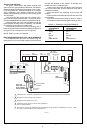
To connect the D80B, follow the wiring diagrams sup-
plied with the vent damper or see Fig. 7 for typical connec-
tions.
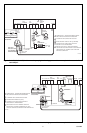
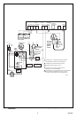
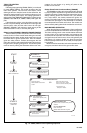
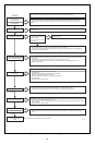
Connect Ignition Module
1. Connect remaining system components to the ignition
module terminals as shown in the appropriate wiring dia-
gram, Figs. 1 to 10.
• Fig. 1 is a basic circuit for a heating only atmos-
pheric burner with S8600F,H,M; S8610F,H;
S8660D or S8670D.
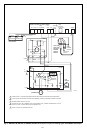
• Fig. 2 shows S8600F,H,M; S8610F,H with vent
damper plug in a heating only atmospheric burner
system with D80D vent damper.
Never
use a vent
damper in an LP gas system or in a fan-assisted
combustion system.
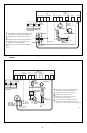
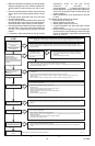
• Figs. 3 and 4 show S8600A,B; S8610A,B with
separate sensor and igniter, with and without the
D80D vent damper.
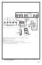
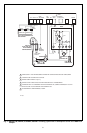
• Figs. 5-10 show S8600F,H,M; S8610F,H; S8660D;
and S8670D in a variety of systems, with alternate
connections for modules with vent damper plug.
Remember, however, that a vent damper should
not be used in an fan-assisted combustion system
or an LP gas system and that the vent damper plug
must not be removed except to connect the mod-
ule to a D80D with the plug-in cable. S8600A,B;
S8610A,B can be substituted in these drawings by
simply connecting the igniter and sensor as shown
in Figs. 3 and 4.
2.Refer to heating appliance manufacturer’s instruc-
tions for wiring auxiliary controls.
3.Adjust thermostat heat anticipator to match system
current draw. The current draw equals the total current
required for the ignition module (0.2 A) plus the gas control
and any other auxiliary equipment in the control circuit.
Connect Gas Control
Use No 18 gauge solid or stranded wire. Use 1/4 in.
female quick connects for module connections. Connect to
gas control terminals as shown in wiring diagrams, using
terminals appropriate to the gas control.
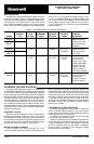
TABLE 2—HONEYWELL PREASSEMBLED IGNITION
CABLES (UL STYLE 3257).
CABLE
PART MODULE IGNITER
NUMBER LENGTH END END
394800-30 30 in. 1/4 in. quick Rajah connec-
connect, tor receptacle,
insulated 90 deg. rubber
boot
394801-30 30 in. 1/4 in. quick Rajah connec-
connect, tor receptacle,
insulated straight rubber
boot
TABLE 3—RECOMMENDED IGNITION CABLE FOR
FIELD ASSEMBLY.
TEMPERATURE
CABLE VOLTAGE RATING
TYPE RATING (rms) C F
UL Style 3217 10,000 150 302
UL Style 3257 10,000 250 484