


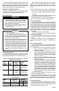
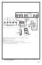
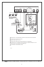
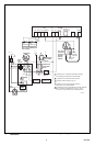
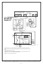
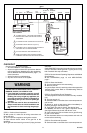
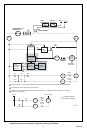
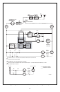
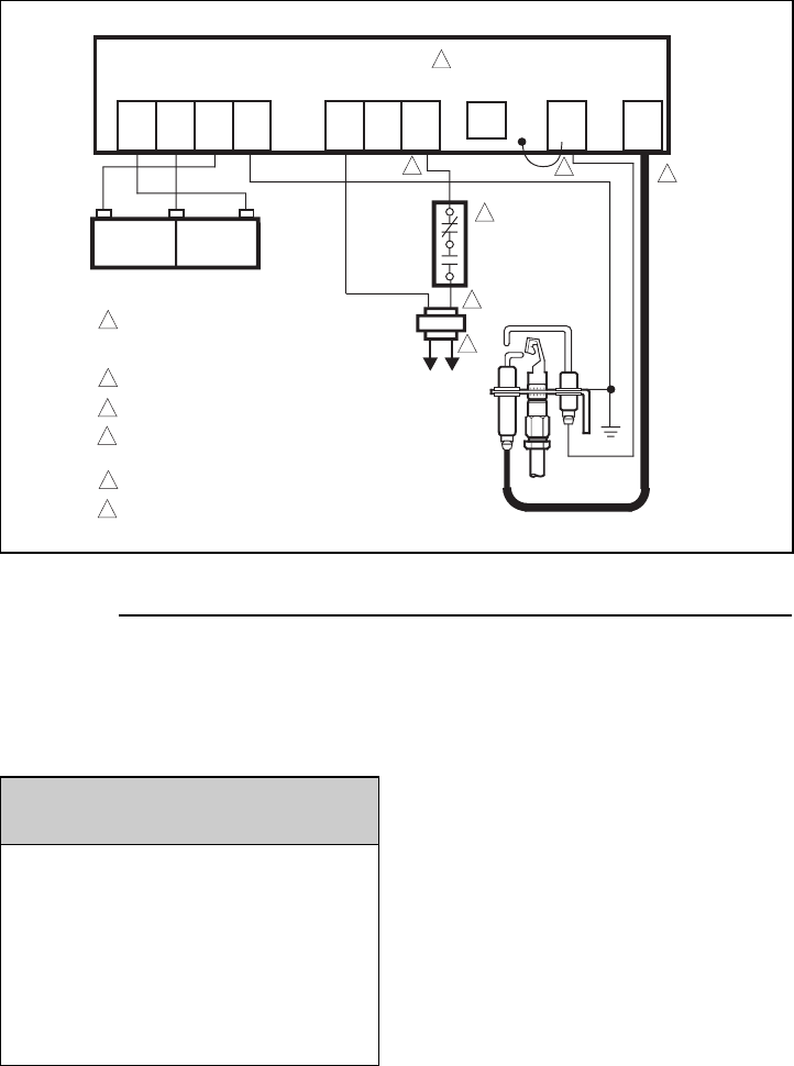
Fig. 10—S8600F,H,M; S8610F,H; S8660D; S8670D connections in a commercial water heater control system.
11 69-0463
CHECKOUT
Check out the gas control system:
• At initial installation of the appliance.
• As part of regular maintenance procedures. Mainte-
nance intervals are determined by the application.
See PLANNING THE INSTALLATION, page 1, for
more information.
• As the first step in troubleshooting.
• Any time work is done on the system.
WARNING
FAILURE TO HEED THESE WARNINGS MAY
CAUSE FIRE OR EXPLOSION WITH PROPERTY
DAMAGE, INJURY, OR LOSS OF LIFE.
1. If you smell gas or suspect a gas leak, turn off
gas at manual service valve and evacuate the
building. Do not try to light any appliance, do
not touch any electrical switch or telephone in
the building until you are sure no spilled gas
remains.
2. Gas leak test must be done as described in
Steps 1 and 5 below on initial installation and
any time work is done involving the gas pip-
ing.
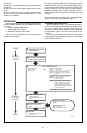
STEP 1: Perform Visual Inspection.
❏ With power off, make sure all wiring connections are
clean and tight.
❏ Turn on power to appliance and ignition module.
❏ Open manual shutoff valves in the gas line to the
appliance.
❏ Do gas leak test ahead of gas control if piping has been
disturbed.
GAS LEAK TEST: Paint pipe joints with rich soap and water
solution. Bubbles indicate gas leak. Tighten joints to stop
leak. Recheck with soap and water.
STEP 2: Review Normal Operating Sequence and Module
Specifications.
❏ See OPERATION, page 12, and APPLICATION,
page 1.
STEP 3: Reset the Module.
❏ Turn the thermostat to its lowest setting.
❏ Wait one minute.
As you do Steps 4 and 5, watch for points where operation
deviates from normal. Refer to Troubleshooting Chart to
correct problem.
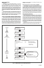
STEP 4: Check Safety Shutoff Operation.
This step applies to lockout and continuous retry modules
only.
❏ Turn gas supply off.
❏ Set thermostat or controller above room temperature to
call for heat.
❏ Watch for spark at pilot burner either immediately or
following prepurge. See device label.
❏ Time spark from start to shutoff. See device label.
On S8600M, wait 6 min. nom. Ignition sequence should
start again followed by shutoff after 90 sec. max.
❏ Open manual gas cock and make sure no gas is flowing
to pilot or main burner.
❏ Set thermostat below room temperature and wait one
minute before continuing.
STEP 5: Check Normal Operation.
❏ Set thermostat or controller above room temperature to
5
M
V
MV/P
V
PV
GND
(BURNER)
24V
GND
24
V
TH-W
(OPT)
VENT
DAMPER
PLUG
SPARK
4
S8610
U
1
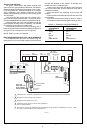
POWER SUPPLY. PROVIDE DISCONNECT
MEANS AND OVERLOAD PROTECTION AS
REQUIRED.
ALTERNATE LIMIT CONTROLLER LOCATION.
MAXIMUM CABLE LENGTH 3 ft [0.9 m].
CONTROLS IN 24V CIRCUIT MUST NOT BE IN
GROUND LEG TO TRANSFORMER.
DO NOT REMOVE VENT DAMPER PLUG.
REMOVE JUMPER AND CONNECT SENSE
TERMINAL ON TWO ROD APPLICATION ONLY.
1
2
3
4
M1179A
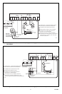
L1
(HOT)
L2
4
L8100
3
2ND
OPERATOR
1ST
OPERATOR
PILOT
COM
MAIN
VALVE
DUAL VALVE COMBINATION
GAS CONTROL
SENSE
6
5
6
ECO
CONTROLLER
2
GROUND
PILOT GAS
SUPPLY