


EXHIBIT B
PROCEDURE FOR INSTALLING AUTOMATIC INTERMITTENT PILOT SYSTEMS
Prior to beginning this procedure, a preliminary ex-
amination of the appliance and the automatic intermit-
tent pilot system should be made to determine that the
automatic intermittent pilot system can be properly
applied to the appliance.
This procedure is intended as a guide to aid in safely
installing a listed automatic intermittent pilot system on
an existing listed appliance equipped with an atmos-
pheric gas burner(s) and not of the direct vent type.
This procedure is based on the assumption that the
history of the specific installation has been one of safe
and satisfactory operation.
This procedure is predicated on central furnace and
boiler installations, and it should be recognized that
generalized procedures cannot anticipate all situations.
Accordingly, in some cases, deviation from this proce-
dure may be necessary to determine safe operation of
the equipment.
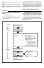
The following steps should be followed in making the
modifications:
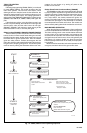
1. Perform a safety inspection of the existing appli-
ance installation. See Exhibit A for a recommended
procedure for such a safety inspection.
2. Shut off all gas and electricity to the appliance. To
shut off gas, use the shutoff valve in the supply line to the
appliance. Do not use the shutoff valve which is pro-
vided as part of a combination control.
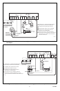
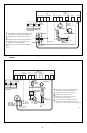
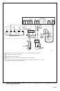
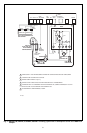
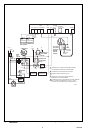
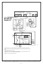
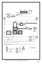
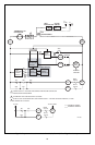
3. Install the automatic intermittent pilot system in
strict accordance with the manufacturer’s installation
instructions.
4. Turn on all gas and electricity to the appliance.
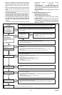
5. Determine that the appliance transformer has
adequate capacity by following the steps outlined be-
low:
a. Compute the approximate current draw by adding
the current draw of the automatic intermittent pilot
system to (1) the current draw of the associated
valving, and (2) the current draw of any relays or
other devices operated by the transformer.
b. Multiply the total current draw as computed above
by 24 V to determine the total VA (volt-ampere)
required.
c. The total VA (volt-ampere) required should be
equal to or less than the VA rating of the transformer.
d. If the total VA (volt-ampere) required is greater
than the VA rating of the transformer, the transformer
must be replaced with a Class 2 transformer of
adequate rating.
6. Check the heat anticipator in the comfort thermo-
stat to determine if it is properly adjusted to the current
draw of the control system. Follow the thermostat
manufacturer’s instructions.
7. Make certain wiring connections are tight and
wires are positioned and secured so they will not be able
to contact high temperature locations.
8. Conduct a Gas Leakage Test of the appliance
piping and control system downstream of the shutoff
valve in the supply line to the appliance.
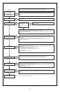
9. a. Adjust the thermostat to its highest tempera-
ture setting, and test manifold pressure and adjust
the pressure regulator to match original input as
required (refer to Exhibit A, step 9b).
b. Visually determine that main burner is burning
properly; i.e., no floating, lifting or flashback. Ad-
just the primary air shutter(s) as required.
10. If the appliance is equipped with high and low
flame control or flame modulation, check for proper main
burner operation at both high and low flame.
11. Determine that the pilot is igniting and burning
properly and that main burner ignition is satisfactory by
interrupting and re-establishing the electrical supply to
the appliance in any convenient manner. Make this
determination with the appliance burner both cold and
hot. Perform this step as many times as is necessary to
satisfy yourself that the automatic intermittent pilot sys-
tem is operating properly.
12. Test the pilot safety device (1) to determine if it is
operating properly, and (2) for turndown characteristics
according to the manufacturer’s installation instructions.
No adjustments should be made other than those rec-
ommended by the system manufacturer.
13. Sequence the appliance through at least three
operating cycles.
14. Applicable only to furnaces. Check both the limit
controller and the fan controller for proper operation.
Limit control operation can be checked by blocking the
circulating air inlet or temporarily disconnecting the
electrical supply to the blower motor and determining
that the limit controller acts to shut off the main burner
gas.
15. Applicable only to boilers.
a. Determine that the circulating water pumps are
in operating condition.
b. Test low water cutoffs, automatic feed water
controls, pressure and temperature limit control-
lers and relief valves in accordance with the
manufacturer’s recommendation to determine
they are in operating condition.
16. Add the labels (see 1.6.1-n and -o) on the appli-
ance.
EXHIBIT B OF ANSI STANDARD Z21.71 FOR AUTOMATIC INTERMITTENT PILOT IGNITION SYSTEMS FOR FIELD
INSTALLATION.
Home and Building Control Home and Building Control
Honeywell International, Inc. Honeywell Limited—Honeywell Limitée
1985 Douglas Drive North 35 Dynamic Drive
Golden Valley, MN 55422 Scarborough, Ontario M1V 4Z9