


4
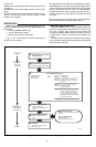
Ground Control System
The igniter, flame sensor and ignition module must
share a common ground with the main burner. Use thermo-
plastic insulated wire with a minimum rating of 105° C [221°
F] for the ground wire; asbestos insulation is not accept-
able. If necessary, use a shield to protect the wire from
radiant heat generated by the burner. Connect the ground
wire as follows:
1.Fit one end of the ground wire with a female 1/4 in.
quick-connect terminal and connect it to the male quick-
connect GND(BURNER) terminal on the ignition module.
2.Strip the other end of the wire and fasten it under the
igniter bracket mounting screw. If necessary, use a shield
to protect the ground wire from radiant heat.
3.The burner serves as the common grounding area. If
there is not good metal-to-metal contact between the burner
and ground, run a lead from the burner to ground.
NOTE: “Earth” ground is not required.
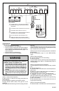
REPLACING MODULE WITH TH-R, TH-W TERMINALS
On modules that do not have a vent damper plug, the
thermostat must be connected between the transformer
and the 24V terminal on the module. To change out a
module with TH-R, TH-W terminals:
1.Remove the wires from the 25V(2) and TH-R termi-
nals on the old module. Connect these two wires with a
solderless connector.
2.Tag and remove the remaining wires from the old
module.
3. Remove the old module and mount the new one in the
same location.
4.Reconnect the remaining wires as shown in Table 4.
5.Increase the thermostat anticipator setting by 0.2 A.
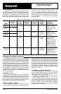
TABLE 4—TERMINAL CROSS REFERENCE.
TERMINAL ON TERMINAL ON
OLD MODULE: NEW MODULE:
25 V (1) 24 V (GND)
TH-W 24 V
MV MV
MV/PV MV/PV
PV PV
GND (Burner) GND (Burner)
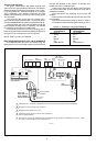
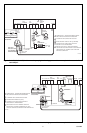
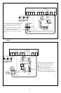
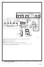
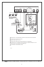
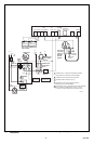
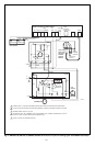
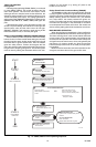
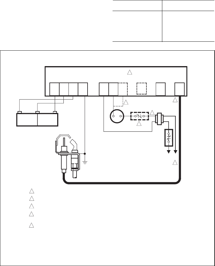
Fig. 1—S8600F,H,M; S8610F,H; S8660D; S8670D connections in a heating system with an atmospheric burner.
THERMOSTAT
L1
(HOT)
L2
1
LIMIT
CONTROLLER
2
4
5
MV MV/PV PV
GND
(BURNER)
24V
GND
24V
TH-W
(OPT)
VENT
DAMPER
PLUG (OPT)
SPARK
5
S8600F,H,M; S8610F,H; S8660D; S8670D
2ND
OPERATOR
1ST
OPERATOR
PILOT COM
MAIN
VALVE
DUAL VALVE COMBINATION
GAS CONTROL
PILOT BURNER
GROUND
PILOT GAS
SUPPLY
Q345, Q346,
Q348, Q362, Q381
PILOT BURNER/
IGNITER-SENSOR
3
POWER SUPPLY. PROVIDE DISCONNECT MEANS AND OVERLOAD PROTECTION AS REQUIRED.
ALTERNATE LIMIT CONTROLLER LOCATION.
MAXIMUM CABLE LENGTH 3 ft [0.9 m].
CONTROLS IN 24V CIRCUIT MUST NOT BE IN GROUND
LEG TO TRANSFORMER.
FOR MODULE WITH TH-W TERMINAL AND VENT DAMPER PLUG, CONNECT THERMOSTAT TO TH-W. LEAVE
24V OPEN. DO NOT REMOVE VENT DAMPER PLUG.
1
2
3
4
5
M1175C