


69-1233—2 G.R. Rev. 5-00 www.honeywell.com
Home and Building Control Home and Building Control
Honeywell Inc. Honeywell Limited-Honeywell Limitée
Honeywell Plaza 155 Gordon Baker Road
P.O. Box 524 North York, Ontario
Minneapolis, MN 55408-0524 M2H 3N7
R7184A,B,P,U INTERRUPTED ELECTRONIC OIL PRIMARY
Printed in U.S.A. on recycled
paper containing at least 10%
post-consumer paper fibers.
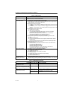
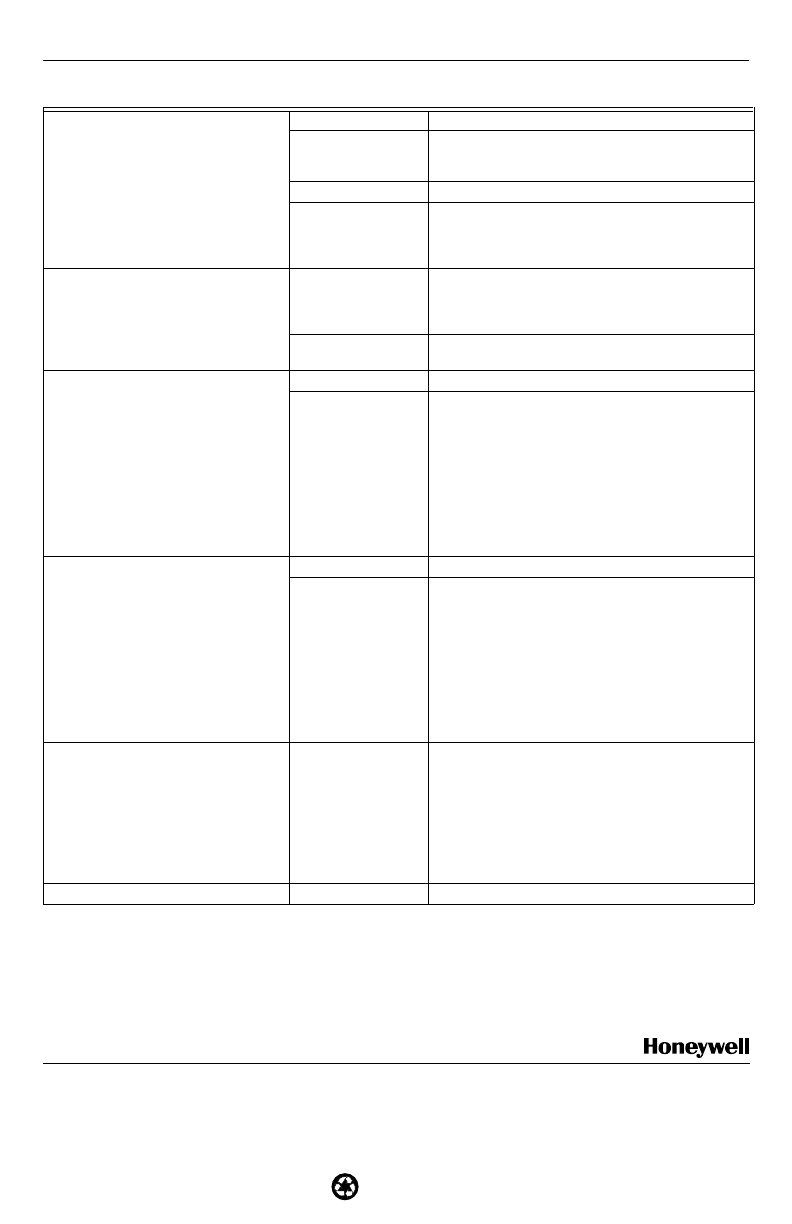
7. Listen for spark after burner turns on
(after a 2 second delay.
Ignition is off. Spark ignitor could be defective. Check for line
voltage at ignitor terminals. If line voltage is present,
replace R7184.
Ignition is on. Go to step 8.
Ignition is on, but no
oil is being sprayed
into the combustion
chamber.
Wait for Valve On Delay to complete (R7184B,P, and
U). Check oil valve, oil valve wiring, pump and oil
supply.
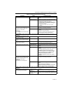
8. Check indicator light after flame is
established, but before oil primary
control locks out.
Indicator light is on
until the control locks
out and starts flashing
during lockout.
Replace R7184.
Indicator light stays
off.
Go to step 9.
9. Check cad cell sighting for view of
flame.
• Disconnect line voltage power and
open line switch.
• Unplug cad cell and clean cad cell
face with soft cloth. Check sighting
for clear view of flame. Place cad cell
back in socket.
• Reconnect line voltage power and
close line switch.
• Start burner.
Burner locks out. Go to step 10.
Burner keeps running. System is okay.
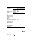
10. Check cad cell.
• Disconnect line voltage power and
open line switch.
• Remove existing cad cell and replace
with new cad cell.
• Disconnect all wires from thermostat
terminals to be sure there is no call
for heat.
• Reconnect line voltage power and
close line switch.
• Expose new cad cell to bright light,
such as a flashlight.
Indicator light is on. Place control back on burner. Go to step 6.
Indicator light is off. Go to step 11.
11. Check cad cell bracket assembly.
• Disconnect line voltage power and
open line switch.
• Remove cad cell wires from quick-
connect connectors on the R7184
and leave control leadwires open.
• Apply power to device.
• Place jumper across cad cell
terminals after burner motor turns on.
Indicator light is on. Replace cad cell bracket assembly. Refer to
TRADELINE® Catalog for bracket part numbers.
Indicator light is off. Replace R7184.
Table 5. Troubleshooting Information (Continued).
Procedure Status Corrective Actions