


R7184A,B,P,U INTERRUPTED ELECTRONIC OIL PRIMARY
69-1233—24
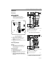
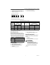
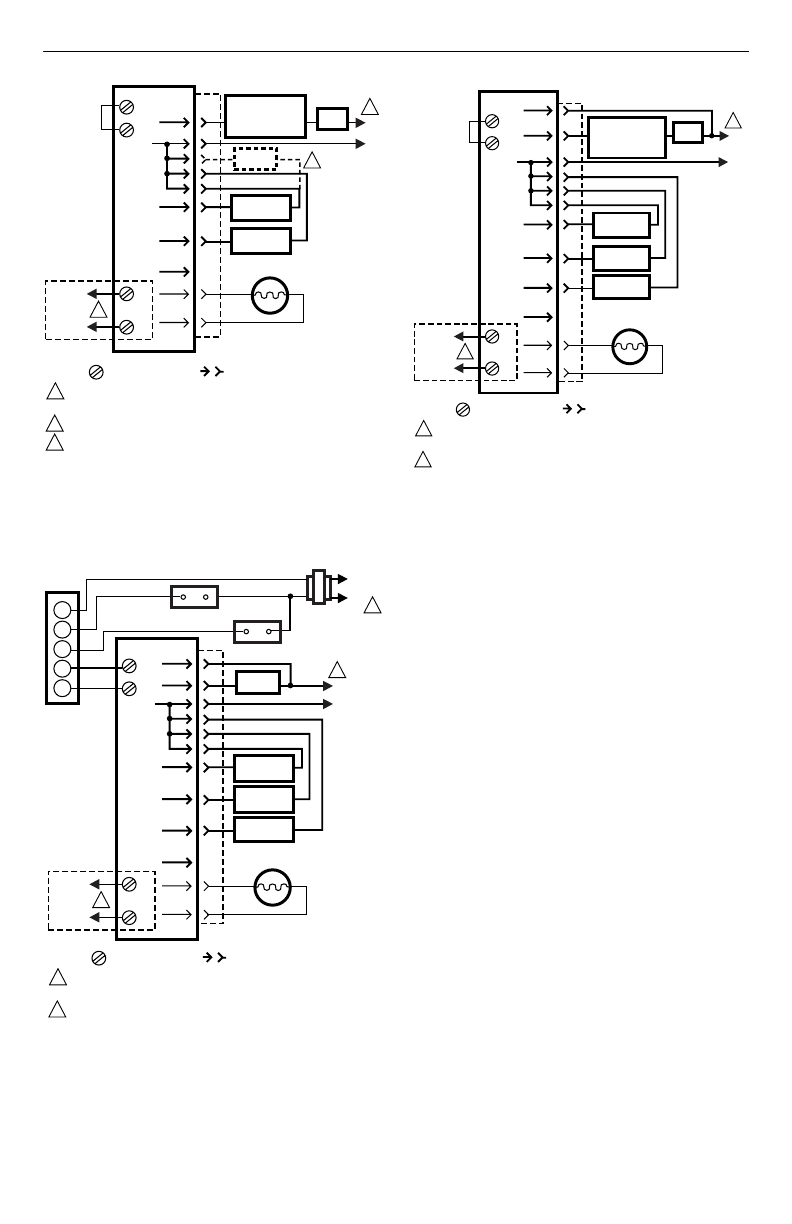
Fig. 5. Typical wiring diagram for line voltage
Aquastat® thermostat and R7184 for an oil burner
system.
Fig. 6. Typical wiring diagram for 24 Vac thermostat
and R7184 for valve-on delay/burner motor off oil
burner system.
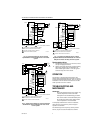
Fig. 7. Typical wiring diagram for line voltage
Aquastat® thermostat and R7184B,P,U for valve-on
delay/burner motor-off delay oil burner system.
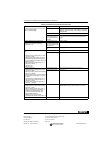
Simulate ignition failure:
1.
Follow starting procedure to turn on burner, but do
not open oil supply hand valve.
2.
Observe that safety switch locks out approximately
within safety switch timing as indicated on the
label. Indicator light flashes at 1 Hz rate. Ignition
and motor stop and oil valve closes.
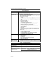
OPERATION
The R7184 is a microprocessor-based control. The
indicator light provides diagnostic information for lockout,
recycling and patented cad cell status. There is a manual
reset button to exit the lockout mode and enter the idle
mode. Operation is shown in Table 4.
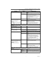
TROUBLESHOOTING AND
MAINTENANCE
IMPORTANT:
Due to the potential hazard of line voltage, only
a trained, experienced service technician
should perform the troubleshooting procedure.
This control contains no field-serviceable parts.
Do not attempt to take it apart. Replace entire
control if operation is not as described.
To completely troubleshoot an oil burner installation,
check the burner and oil primary control for proper
operation and condition.
The indicator light on the oil primary control provides
lockout, recycle and cad cell indications as follows:
L2
1
R7184
IGNITOR
M17184B
L1
HOT
1
CAD
CELL
2
2
BURNER
MOTOR
L2
BURNER
MOTOR
INTERMITTENT
IGNITOR
INTERRUPTED
CAD
CELL
L1
JUNCTION
BOX
ALARM
T
T
LEGEND:
TO
REMOTE
ALARM
CIRCUIT
SCREW TERMINAL
1/4 IN. QUICK CONNECT TERMINAL
LIMIT
JUMPER
LINE VOLTAGE
THERMOSTAT
OR AQUASTAT®
CONTROL
POWER SUPPLY. PROVIDE DISCONNECT MEANS
AND OVERLOAD PROTECTION AS REQUIRED.
OPTIONAL FEATURE ON SELECT MODELS.
VALVE MAY BE ADDED AS SHOWN.
3
3
VALVE
L2
POWER SUPPLY. PROVIDE DISCONNECT MEANS
AND OVERLOAD PROTECTION AS REQUIRED.
OPTIONAL FEATURE ON SELECT MODELS.
1
R7184
M17185A
L1
HOT
1
CAD
CELL
2
2
OIL
VALVE
BURNER
MOTOR
IGNITOR
L2
BURNER
MOTOR
INTERMITTENT
IGNITOR
VALVE
INTERRUPTED
CAD
CELL
LIMIT
L1
JUNCTION
BOX
ALARM
T
T
LEGEND:
TO
REMOTE
ALARM
CIRCUIT
SCREW TERMINAL
1/4 IN. QUICK CONNECT TERMINAL
LIMIT
T8600
RC
G
Y
R
W
L1
(HOT)
L2
1
FAN RELAY
COOLING
CONTROL
L2
POWER SUPPLY. PROVIDE DISCONNECT MEANS
AND OVERLOAD PROTECTION AS REQUIRED.
OPTIONAL FEATURE ON SELECT MODELS.
1
R7184
M17186A
CAD
CELL
2
2
OIL
VALVE
BURNER
MOTOR
IGNITOR
L2
BURNER
MOTOR
INTERMITTENT
IGNITOR
VALVE
INTERRUPTED
CAD
CELL
LIMIT
L1
JUNCTION BOX
ALARM
T
T
LEGEND:
TO
REMOTE
ALARM
CIRCUIT
SCREW TERMINAL
1/4 IN. QUICK CONNECT TERMINAL
L1
HOT
1
JUMPER
LINE VOLTAGE
THERMOSTAT
OR AQUASTAT®
CONTROL
LIMIT