


R7184A,B,P,U INTERRUPTED ELECTRONIC OIL PRIMARY
3 69-1233—2
CHECKOUT
Start System
WARNING
Fire Hazard.
Can cause serious injury or death.
Make sure combustion chamber is free of oil
and/or oil vapor before starting system.
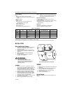
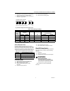
Fig. 2. Wiring terminals.
1.
Open hand valve in oil supply line.
2.
Make sure system is powered. Check circuit
breaker or fuse and close system switch, if
provided.
3.
Set thermostat to call for heat.
4.
Make sure burner lights and operates until call for
heat ends.
Check Safety Features
Safe Start
1.
Place a jumper across cad cell terminals.
2.
Follow procedure to turn on burner. Burner must
not start, indicator light turns on and control
remains in Idle Mode.
Simulate flame failure:
1.
Follow procedure to turn on burner.
2.
Close hand valve in oil supply line.
3.
Device enters recycle mode.
4.
Device tries to restart system after approximately
60 seconds.
5.
Safety switch locks out approximately in safety
switch timing indicated on label. Indicator light
flashes at 1 Hz rate. Ignition and motor stop and oil
valve closes.
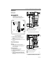
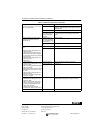
Fig. 3. Wiring for typical oil-fired boiler.
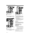
Fig. 4. Typical wiring diagram for 24 Vac thermostat
and R7184 for an oil-fired forced air system.
INTERRUPTED
INTERMITTENT
BURNER MOTOR
IGNITOR
LIMIT
VALVE
L2
L1
CAD CELL
M16453A
L2
POWER SUPPLY. PROVIDE DISCONNECT MEANS
AND OVERLOAD PROTECTION AS REQUIRED.
OPTIONAL FEATURE ON SELECT MODELS.
1
R7184
IGNITOR
M17182B
L1
1
CAD
CELL
2
2
BURNER
MOTOR
CIRCULATION
PUMP
L2
B2
C2
C1
BURNER MOTOR
IGNITOR
INTERRUPTED
INTERMITTENT
VALVE
VALVE
CAD
CELL
L1
B1
LIMIT
JUNCTION
BOX
ALARM
T
T
T
T
LEGEND:
TO
REMOTE
ALARM
CIRCUIT
SCREW TERMINAL
1/4 IN. QUICK CONNECT TERMINAL
THERMOSTAT
L8148A,C
JUMPER
AQUASTAT®
CONTROLLER
R
W
L2
POWER SUPPLY. PROVIDE DISCONNECT MEANS
AND OVERLOAD PROTECTION AS REQUIRED.
OPTIONAL FEATURE ON SELECT MODELS.
VALVE MAY BE ADDED AS SHOWN.
1
R7184
IGNITOR
M17183B
L1
HOT
1
3
CAD
CELL
2
2
3
BURNER
MOTOR
L2
BURNER
MOTOR
INTERMITTENT
IGNITOR
INTERRUPTED
CAD
CELL
L1
JUNCTION
BOX
ALARM
T
T
LEGEND:
TO
REMOTE
ALARM
CIRCUIT
SCREW TERMINAL
1/4 IN. QUICK CONNECT TERMINAL
LIMIT
VALVE
T8600
RC
G
Y
R
W
L1
(HOT)
L2
1
FAN RELAY
COOLING
CONTROL