


R7184A,B,P,U INTERRUPTED ELECTRONIC OIL PRIMARY
69-1233—2 2
Electrical Ratings:
Inputs:
Voltage: 102 to 132 Vac, 120 Vac nominal.
Current: 100 mA plus burner motor, valve and ignitor
loads.
Frequency: 60 Hz.
Outputs:
Relay Contacts:
Burner: 120 Vac, 10 full load amperes (FLA),
60 locked rotor amperes (LRA).
Valve: 120 Vac, 1A.
Ignitor: 120 Vac, 360 VA.
Alarm: 30 Vac, 2A.
Thermostat Current Available: 100 mA.
NOTE: Reduce burner FLA rating by Ignitor load. For
example, if the ignitor draws 3A (120 Vac, 360
VA), reduce the burner motor FLA to 7A.
Environmental Ratings:
Operating Ambient Temperature: -40°F (-40°C) to
+147°F (+64°C).
Shipping Temperature: -20°F (-29°C) to +150°F (+66°C).
Humidity: 90% relative humidity at 95°F (93°C)
noncondensing.
Approvals:
Underwriters Laboratories Inc.: Recognized.
Canadian Underwriters Laboratories Inc.
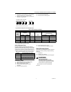
Table 1. R7184 Models.
a
Some select models may have a delay enable/disable switch.
b
Standard timings. Other timing may be available on select models.
c
Select models are provided with a T-T jumper which can be disabled by cutting with a pair of side-cutting pliers.
INSTALLATION
When Installing this Product...
1.
Read these instructions carefully. Failure to follow
instructions can damage product or cause a
hazardous condition.
2.
Check ratings given in these instructions and on
product to make sure product is suitable for your
application.
3.
Make sure installer is a trained, experienced
service technician.
4.
Use these instructions to check out product
operation after installation.
WARNING
Electrical Shock Hazard.
Can cause serious injury or death.
Disconnect power supply before beginning
installation to prevent electrical shock or
equipment damage.
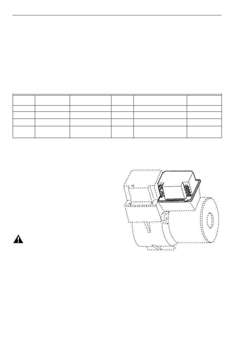
Location
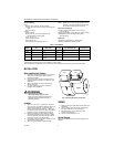
1.
Mount on a 4 in. by 4 in. junction box, directly on
the main burner or inside the appliance cabinet. In
replacement applications, mount in the same
location as the old control. See Fig. 1. Make sure
the operating temperatures are within the ambient
temperature range (see Specifications section).
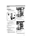
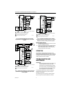
2.
Before mounting the control, make line voltage
connections as shown in Fig. 2 through 7. Splice
lines with solderless connectors. Do not exceed
load ratings shown on the device label.
3.
If necessary, use the control as a template to mark
and drill new mounting holes.
4.
Mount using No. 6 screws (obtained locally).
Fig. 1. Mounting R7184 on junction box.
WIRING
1.
Make sure wiring complies with all local codes and
ordinances.
2.
After mounting, make low voltage connections to
the screw terminals (see Fig. 2 through 7).
3.
Strip leads 3/8 in. (10 mm) and insert under
terminal screw. See Fig. 1.
4.
Connect thermostat leads to T-T.
Switch Settings
Figure 8 and Table 2 provide the switch settings for the
R7184U.
Model
Valve-on delay
(sec)
Burner motor-off
delay (min)
Alarm
Contacts
Typical Wiring Diagram
Fig. Reference No.
Thermostat
Terminals T-T
R7184A None None None 3,4,5 Yes
R7184B 15 None None 3,6,7
Yes
c
R7184P
a
15
0/2/4/6
b
Optional 3,6,7 Yes
R7184U Selectable 0 or 15 Selectable 0 or
0,2,4,6
b
Yes 3,6,7 Yes
R7184S7184
BURNER
M17180A