


Programming
MS-9200UDLS PN 52750:E1 01/27/09 85
As an example, the user could quickly enter ‘FLR_3_ROOM 305’ as follows:
1. The cursor is on the first letter of the Adjective field. Press the zero key twice to
display FLR_3
2. With the cursor on the first letter of the Noun field, press the zero key twice to
recall the display ROOM_304. The cursor automatically jumps from the first to
the last letter of the Noun field
3. With the cursor on the last letter of the Noun field, press the zero key again to
increment the room number to 305
4. Press the right arrow key to advance the zone field
5. Select a zone number from 00 to 99. Z00 (default zone) is the general alarm
zone. Z01 through Z99 may be selected to link software zones
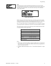
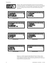
3.6.2.2.4 Edit Module Screen for Control Modules
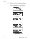
The programmer can change a module’s existing or factory default programming by
pressing 3 in the Modules Screen. The following screen will be displayed:
A flashing cursor will appear in the position of the first asterisk to the left.
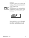
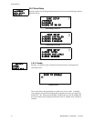
The programmer keys in the three digit module address, such as 002. When the last
digit is keyed-in, if the selected address corresponds to a control module, a screen
displaying information about the control module with the selected address will be
displayed as illustrated in the following:
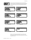
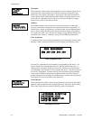
In the preceding example:
Normal - indicates that the module with the selected address is physically
installed on the SLC and communicating with the control panel (enabled)
<ADJ><NOUN> - represents the adjective and noun, which have been
programmed, describing the location of the displayed device
Control - indicates that the selected module is a control module
S or * - represents Silenceable (S) or Nonsilenceable (*)
W or * - represents Waterflow Timer Delay (W = Waterflow Timer Delay
enabled, * = Waterflow Timer Delay disabled)
ZNNN - represents the first of five possible software zones that the module is
assigned to (NNN = the three digit zone number from 000 - 099)
1M002 - represents the Loop, Device type and Device address (1 = SLC Loop,
M=Module and 002 = Module Address 02)
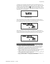
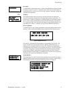
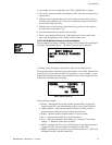
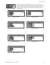
MODULES
1=ADD
2=DELETE
3=EDIT
Modules Screen
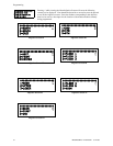
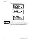
EDIT MODULE
ENTER MODULE ADDRESS
***
Edit Module Screen
NORMAL CONTROL
<ADJ><NOUN>
ZNNN
SW 1M002
Edit Control Screen #1