


Installation of Optional Modules Program Options via DIP Switch
MS-2/MS-4 PN 51512:E 01/18/05 31
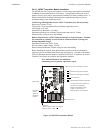
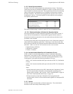
SECTION 3 Program Options via DIP Switch
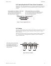
This section describes the programming options available via DIP switch settings. The
FACP can be field programmed using option DIP switches SW1, SW2 and SW3 which
are located in the bottom right side of the main circuit board. Refer to the following
illustration for switch locations and DIP switch placement in the ON and OFF
positions.
NOTICE TO USERS, INSTALLERS, AUTHORITIES HAVING JURISDICTION AND OTHER INVOLVED PARTIES
This product incorporates field-programmable software. In order for the product to comply with the requirements in the
Standard for Control Units and Accessories for Fire Alarm Systems, UL 864, certain programming features or options must be limited
to specific values or not used at all as indicated below.
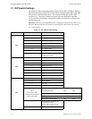
Program feature or option Permitted in UL 864? (Y/N) Possible settings Settings permitted in UL 864
Alarm Verification Y Refer to Table 3.1 on page 32
and Table 3.2 on page 33
Alarm Verification OFF
ON
ON
ON
12345678
12345678
12345678
ON
ON
12345678
12345678
ON
ON
12345678
12345678
SUPERVISORY
SUPERVISORY
SUPERVISORY
SUPERVISORY
TROUBLE
TROUBLE
TROUBLE
TROUBLE
MAINTENANCE
MAINTENANCE
MAINTENANCE
MAINTENANCE
FIRE ALARM
FIRE ALARM
AC
POWER
NAC
DISABLE
NAC
FAULT
SYSTEM
TROUBLE
POWER
TROUBLE
WAL K
TEST
ALARM
SILENCE
ZONE
DISABLE
FIRE ALARM
FIRE ALARM
RESET
WALK
TEST
ALARM
SILENCE
ACK
ZONE 1
ZONE 2
ZONE 3
ZONE 4
ZONE
ENABLE/DISABLE
3
4
2
1
TB1
TB2
TB3
TB5
TB6
TB7
J1
B+ B- B+ B-
NAC 1 NAC 2
+ - + -
Nonreset Reset
B+ B- B+ B-
ZONE 1 ZONE 2
B+ B- B+ B-
ZONE 3 ZONE 4
C TRBL NORM
TROUBLE
C NC NO
ALARM SUPV
C NC NO
J3
J5
J4
J8
J7
J9
TB8
J6
JP1
JP3
SW1
SW
1
BATTERY
HOT NEUT EARTH
TRANSFORMER 1TRANSFORMER 2
SW2
SW2
SW3
SW3
JP2
EARTHBATTCHG
CLASS A
CONVERTER
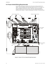
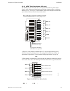
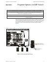
Figure 3.1 Field Programming DIP Switches
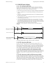
Switches 1 through 7
shown in OFF position
Switch 8 shown in
ON position
ms4switc.cdr