


Input Circuits Installation
MS-2/MS-4 PN 51512:E 01/18/05 21
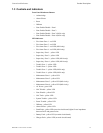
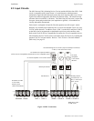
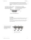
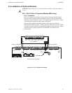
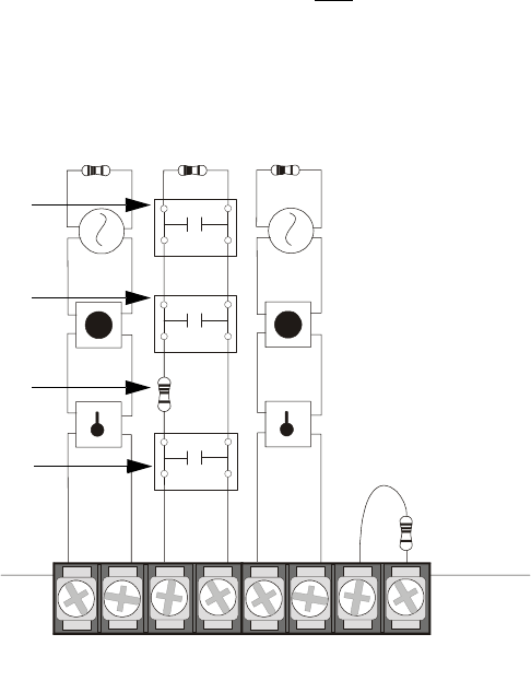
Combination Waterflow/Supervisory Zone
A combination Waterflow/Supervisory circuit allows an FACP to distinguish between
an Alarm switch (waterflow device) and a Supervisory switch (tamper) installed on the
same circuit. The following figure illustrates the wiring of Zone 2 as a Style B (Class
B) Waterflow/Supervisory circuit. Note that only
Zone 1 on the MS-2 and Zone 2 on
the MS-4 can be configured in this manner.
Requirements for the Combination Waterflow/Supervisory circuit are as follows:
The Waterflow Alarm Switch(es) must connect to the FACP Initiating Device
Circuit before the In-Line Resistor as shown in Figure 2.5
The Waterflow Supervisory Switch(es) must connect to the FACP Initiating
Device Circuit after the In-Line Resistor as shown in Figure 2.5
Program the FACP Initiating Device Circuit #1 on the MS-2 or Circuit #2 on
the MS-4 as a Combination circuit by placing SW1 DIP switch 8 to the ON
position as described in "SW1 DIP Switch Settings" on page 34
Waterflow Alarm Switch activation causes the panel to latch into alarm until
the alarm condition is cleared and the FACP is reset
Supervisory Switch activation causes the panel to track the supervisory
condition, that is, the panel will clear when the supervisory condition is
cleared (if FACP is programmed for Autoresettable Supervisory)
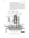
TB3
B+ B- B+ B-
ZONE 1 ZONE 2
B+ B- B+ B-
ZONE 3 ZONE 4
Class B Initiating Device Circuits (supervised and power-limited)
4.7 KΩ, ½ watt resistor P/N:71252
In-Line-Resistor
1.2 KΩ, ½ watt resistor P/N: 75579
Alarm Switch
(waterflow)
Dummy load all unused
circuits - 4.7 KΩ, ½ watt
resistor (P/N: 71245)
Figure 2.5 Style B Combination Circuit on Zone 2 of the MS-4
Supervisory Switch
(tamper)
Supervisory Switch
(tamper)
Note: Zones 3 & 4
on MS-4 only
ms-4zon1.cdr