


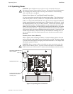
Operating Power Installation
MS-2/MS-4 PN 51512:E 01/18/05 19
2.2 Operating Power
WARNING: Several different sources of power can be connected to this panel.
Disconnect all sources of power before servicing. The panel and associated equipment
may be damaged by removing and/or inserting cards, modules or interconnecting
cables while this unit is energized.
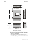
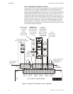
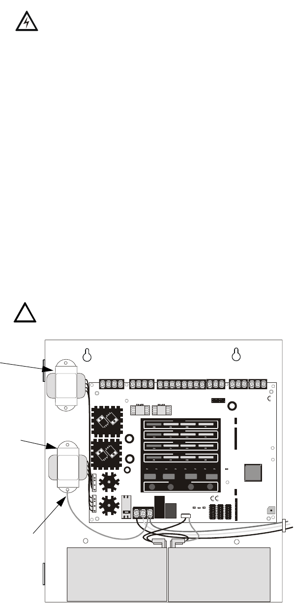
Primary Power Source (AC) and Earth Ground Connections
AC power connections are made inside the control panel cabinet. The primary power
source for the panel is 120 VAC, 50/60 Hz, 2.3 amps for the MS-2/MS-4 or 240 VAC,
50 HZ, 1.15 amps for the MS-2E/MS-4E. Run a pair of wires (with ground conductor)
from the protected premises main breaker box to TB8 of the main circuit board. As per
the National Electrical Code, use 14 AWG (2.00 mm
2
, 1.6 mm O.D.) or heavier gauge
wire with 600V insulation. No other equipment may be connected to this circuit. In
addition, this circuit must be provided with overcurrent protection and may not contain
any power disconnect devices. A separate Earth Ground connection must be made to
ensure proper panel operation and lightning and transient protection. Connect the Earth
Ground wire [minimum 14 AWG (2.00 mm
2
)] to the transformer mounting stud. Do
not use conduit for the Earth Ground connection since this does not provide reliable
protection.
Secondary Power Source (Batteries)
Observe polarity when connecting the battery. Connect the battery cable to J8 on the
main circuit board using the plug-in connector and cable provided. The battery charger
is current-limited and capable of charging sealed lead acid batteries. The charger shuts
off when the system is in alarm.
WARNING: Battery contains sulfuric acid which can cause severe burns to the skin
and eyes and can destroy fabrics. If contact is made with sulfuric acid, immediately
flush the skin or eyes with water for 15 minutes and seek immediate medical attention.
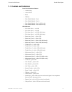
!
ON
12345678
ON
12345678
ON
12345678
SUPERVISORY
SUPERVISORY
SUPERVISORY
SUPERVISORY
TROUBLE
TROUBLE
TROUBLE
TROUBLE
MAINTENANCE
MAINTENANCE
MAINTENANCE
MAINTENANCE
FIRE ALARM
FIRE ALARM
AC
POWER
NAC
DISA BLE
NAC
FAU LT
SYSTEM
TROUBLE
POWER
TROUBLE
WAL K
TEST
ALAR M
SILE NCE
ZONE
DISA BLE
FIRE ALARM
FIRE ALARM
RESET
WALK
TEST
ALARM
SILENCE
ACK
ZONE 1
ZONE 2
ZONE 3
ZONE 4
ZONE
ENABLE/DISABLE
3
4
2
1
TB1
TB2
TB3
TB5
TB6
TB7
J1
B+ B- B+ B-
NAC 1 NAC 2
+ - + -
Nonreset Resettable
B+ B- B+ B-
ZONE 1 ZONE 2
B+ B- B+ B-
ZONE 3 ZONE 4
C TRBL NORM
TROUBLE
C NC NO
ALARM SUPV
C NC NO
J3
J5
J4
J8
J7
J9
TB8
J6
JP1
JP3
SW1
BATTERY
HOT NEUT EARTH
TRANSFORMER 1TRANSFORMER 2
SW2 SW3
JP2
EARTH BATT CHG
CLASS A
CONVERTER
SIGNAL TRANSFORMER
XX-XXX-XXXXXX Rev X
SIGNAL TRANSFORMER
XX-XXX- XXXXXX Rev X
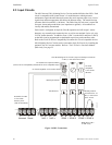
Figure 2.3 Operating Power Connections
Optional second transformer
shown installed
Standard transformer
Earth ground wire shown
connected to transformer
mounting stud
ms4powr.cdr