


L7224A,C; L7248A,C,L OIL AND ELECTRIC BOILER ELECTRONIC AQUASTAT
®
CONTROLLERS
68-0281—16 4
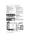
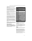
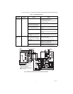
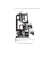
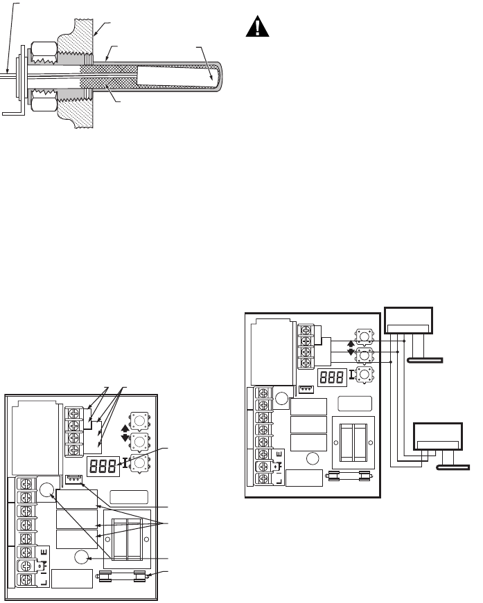
Fig. 4. Replacement sensor installation.
Replacement Sensor Installation
Turn off all power and:
1. Carefully disconnect sensor from circuit board by
pulling gently on the connector.
2. Gently pull sensor from thermo well and through cir-
cuit board by pulling on leadwires.
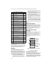
3. Carefully align replacement sensor with hole in cir-
cuit board and guide through Aquastat case and
into well. (See Fig. 5).
4. Make sure sensor is fully seated to bottom of well
(See Fig. 4). Use a small pencil to measure depth of
sensor in well, if necessary.
5. Connect sensor to circuit board by pressing con-
nector on sensor unit into mating connector on cir-
cuit board (See Fig. 5).
6. For remote sensors (flush-mounted Aquastat Con-
trollers) be sure to use 121571AA Clamp (see
Accessories) to securely hold sensor in place.
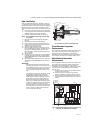
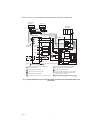
Fig. 5. Circuit board, showing sensor connection and
well holes for vertical mount models.
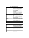
Fuse
The 1 Amp fuse located near the transformer is intended
to protect the EnviraCOM circuit from incorrect wiring. The
Aquastat will continue to function should the fuse blow or
be removed though no EnviraCOM communication will be
possible on the bus and Err 6 will be displayed. See
Table 10.
WIRING
WARNING
Electrical Shock Hazard.
Can cause serious injury or death.
Disconnect power supply before making wiring
connections to prevent electrical shock or
equipment damage.
All wiring must comply with local electrical codes and
ordinances. Do not exceed the specifications in the
Application section when wiring this control. Use wire
rated for 194 °F (90 °C) or higher.
IMPORTANT
The terminals on these Aquastat Controllers are
approved for use with copper wire only.
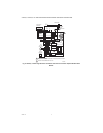
Follow the appropriate wiring diagrams shown on the
inside of the front cover of the L7224A,C; L7248A,C,L or
in Fig. 8–13.
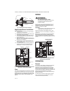
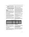
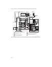
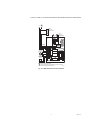
Refer to Fig. 6 for Connections for the optional Outdoor
Reset Module and the Domestic Hot Water (DHW)
module. In subsequent wiring diagrams these modules
will be displayed with a dotted line signifying that they are
optional.
Fig. 6. Wiring the Outdoor Reset Module and the
Domestic Hot Water Module.
OPERATION
General
The L7224A,C and L7248A,C,L Oil Electronic Aquastat
Controllers are primary safety limit-rated devices
designed for use with oil fired boilers with line voltage
burners and circulators. Many boilers do not include
wiring or control compartments as part of the design, but
are provided with an integral, replaceable, immersion well
that is the mounting hardware for the Aquastat
Controllers. Wiring to the other controls is done through
flexible metal conduit.
For boilers that do include a remotely (flush) mounted
control, the wiring may be completed with conduit or
routed behind the boiler sheet metal.
SENSOR WIRES
M22026
HEAT-CONDUCTIVE COMPOUND
(OPTIONAL)
BOILER
IMMERSION
WELL
SENSOR
C1
B1
ZC
L2
LINE
C2
ZR
L1
B2
T
T3
2
1
THERMOSTAT
TERMINALS
ENVIRACOM
TM
TERMINALS
DISPLAY
SENSOR
CONNECTOR
SENSOR HOLES
FUSE
RELAYS
M32187
C1
B1
ZC
L2
LINE
C2
ZR
L1
B2
T
T
3
2
1
1 2 3 OT OT
C7089U1006
OUTDOOR
SENSOR
W8735Y1000 OR W8735S1000
OUTDOOR RESET MODULE
(W8735S1000 SHOWN)
1 2 3 TS TS
W8735S1008
DOMESTIC HOT
WATER MODULE
32003971-003
TEMPERATURE
SENSOR
M34961