


L7224A,C; L7248A,C,L OIL AND ELECTRIC BOILER ELECTRONIC AQUASTAT
®
CONTROLLERS
3 68-0281—16
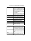
New Installation
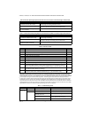
Order well assemblies separately; see Table 1 and form
no. 68-0040, Immersion Wells and Compression Fittings
for Temperature Controllers. Boilers usually have tappings
that allow the well to be mounted horizontally so boiler
water of average temperature can circulate freely over the
well.
1. Turn off all power and drain the boiler, if applicable.
2. If no tapping is provided, prepare properly sized and
threaded tapping near the top of the boiler.
3. Sparingly coat the well threads with pipe dope.
NOTE: Do not attempt to tighten by using the case
as a handle.
4. Install the well in the boiler tapping and tighten
securely.
5. Refill boiler and check for water leakage.
6. Loosen but do not remove the well clamp screw.
7. Fit the case into the well so the clamp on the case
slides over the flange on the well.
8. Securely tighten the clamp screw.
9. Insert the sensor element into the well until it bot-
toms. See Replacement Sensor Installation section
for details. (If necessary, slightly bend the wire
inside the case to hold the sensor against the bot-
tom of the well.)
10. Turn power ON.
11. Set High Limit, Low Limit and Low Limit Differential
to the settings recommended by the boiler OEM.
(See OPERATION section.) (See INSTALLATION
steps 6 and 7.)
12. On L7248L models, adjust ELL option to match your
configuration (see OPERATION section, and Fig. 11
and 13).
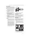
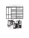
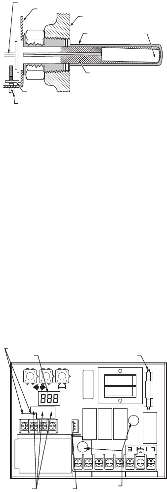
IMPORTANT
Best thermal response is obtained with a well
that snugly fits the sensor. Insert the sensor until
it rests against the bottom of the well. Use a well
of correct length and bend the wiring, if neces-
sary, to hold the bulb against the bottom of the
well.
If the well is not a snug fit on the sensor, use the
heat-conductive compound (furnished with
TRADELINE
®
models) as follows: Fold the
plastic bag of compound lengthwise and twist it
gently. Then snip off end of bag and work the
open end of the bag all the way into the well.
Slowly pull out the bag while squeezing it firmly
to distribute compound evenly in the well. Bend
the wiring, if necessary, to hold the sensor
against the bottom of the well and to hold outer
end of the sensor in firm contact with the side of
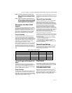
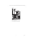
the well. See Fig. 2. Wipe excess compound
from the outer end of the well.
Fig. 2. Position of sensor in immersion well.
Flush-Mounted Aquastat
Replacement
Turn off all power and remove the old control. Refer to the
cover insert of the old control to identify and tag each
external lead as it is disconnected. If the old well is
unsuitable for the new installation, remove it and replace it
with a suitable new well. If the old well is suitable, use it.
Well-Mounted Aquastat
Replacement
Turn off all power and remove the old control. Refer to the
cover insert of the old control to identify and tag each
external lead as it is disconnected. If the old well is
unsuitable for the new installation, remove it and proceed
with instructions for new installation. If the old well is
suitable, use it.
1. Loosen, but do not remove, the well clamp screw on
the side of the control case.
2. Position immersion well clamp snugly over the
flange of the adapter and tighten the clamp screw.
3. Insert the sensor into the well as shown in Fig. 2 or
3. (See Replacement Sensor Installation section for
details.)
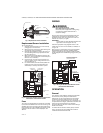
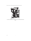
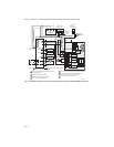
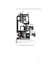
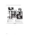
Fig. 3. Circuit board, showing sensor connection and
well holes for horizontal mount models.
SENSOR WIRES
IMMERSION WELL
CLAMP SCREW
IMMERSION
WELL CLAMP
M16120
HEAT-CONDUCTIVE COMPOUND
(OPTIONAL)
CONTROLLER CASE
BOILER
IMMERSION
WELL
SENSOR
C1
B1
ZC
L2
LINE
C2
ZR
L1
B2
T
T3
2
1
THERMOSTAT
TERMINALS
ENVIRACOM
TM
TERMINALS
SENSOR HOLES
FUSE
M32186
SENSOR
CONNECTOR
DISPLAY