


L7224A,C; L7248A,C,L OIL AND ELECTRIC BOILER ELECTRONIC AQUASTAT
®
CONTROLLERS
11 68-0281—16
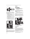
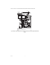
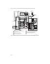
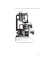
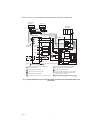
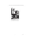
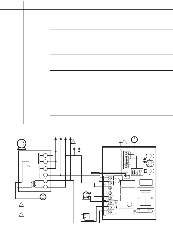
Fig. 9. L7224A,C multizone system with circulator connections.
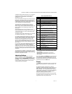
Boiler is hot,
house is cold.
Display is ON. 120 Vac at C1-C2 • 120 Vac at C1-C2, check wiring to pump.
• Wiring OK, is pump running?
• If not, replace the pump.
• If pump is running, check for trapped air or
closed zone valves.
Boiler below the Low Limit
temperature, wait for boiler to go
above Low Limit temperature.
—
Boiler above LL? If yes, check for
120 Vac between ZC and L2.
• If no 120 Vac, replace control.
• If yes, check zone relays, circulators and
wiring.
ELL setting (L7248L only) • Set ELL to Off for multizone system (see Fig.
11).
• Set ELL to On for External Low Limit (see
Fig. 13).
Boiler above LL? If yes, check 120
Vac at ZR-L2 (only L7248L with
ELL set On)
• If no 120 Vac, check C1-C2 (see above).
• If yes, check the External Low Limit control.
Boiler is hot,
no hot potable
water.
Display is ON. Boiler Demand signal from the
water heater (either 120 Vac at
ZR-L2, or 0 Vac on T-T; depends
on installation and “duu” setting)
• 24 Vac on T-T (or 0 Vac on ZR-L2), check
wiring to water heater
• Wiring OK, check the water heater
“duu” setting • Set duu to ON if 120 Vac water heater
demand is connected to ZR
• Set duu to OFF if open/closed water heater
demand is connected to T-T
Check DHW Module and DHW
Sensor
• DHW Module not properly connected and/or
DHW Sensor improperly positioned
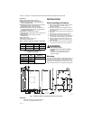
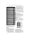
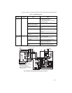
Table 11. Troubleshooting Guide
System
Condition
Diagnostic
Condition Check Action
M27115
POWER SUPPLY. PROVIDE DISCONNECT
MEANS AND OVERLOAD
PROTECTION AS REQUIRED.
1
CONTROL CASE MUST BE CONNECTED
TO EARTH GROUND. USE GROUNDING
SCREW PROVIDED.
2
C1
B1
ZC
L2
LINE
C2
ZR
L1
B2
T
T3
2
1
SENSOR
LINE
VOLTAGE
CIRCULATOR
LINE
VOLTAGE
OIL BURNER
RELAY
2
LOW
VOLTAGE
THERMOSTAT
L7224
3
L1
(HOT)
L2
1
2
1
4
5
6
ZONE 2
LOW VOLTAGE
THERMOSTAT
R845A RELAY ZONE 2
ZONE 2
CIRCULATOR
TO ADDITIONAL R845A
RELAYS FOR OTHER ZONES