


L7224A,C; L7248A,C,L OIL AND ELECTRIC BOILER ELECTRONIC AQUASTAT
®
CONTROLLERS
68-0281—16 2
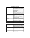
Accessories:
W8735Y1000 Wireless Outdoor Reset Kit
W8735ER1000 Wireless Outdoor Reset Module
C7089R1013 Wireless Outdoor Temperature Sensor
(requires W8735ER1000)
W8735S1000 AquaReset™ Outdoor Reset Kit (includes
50022037-002 Outdoor Reset Module and
C7089U1006 Outdoor Temperature Sensor)
W8735S1008 AquaReset™ Domestic Hot Water Kit
(includes 50022037-005 Domestic Hot Water Module
and 32003971-003 Sensor)
W8735S3000 EnviraCOM™ Alarm Module
C7089U1006 Outdoor Temperature Sensor (used with the
50022037-002)
32003971-003 Temperature Sensor (used with
50022037-005)
Sensor (See Table 2).
120650 Heat Conductive Compound.
121371AA Sensor Well Clamp.
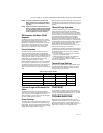
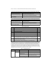
Table 1. Wells for L7224A,C; L7248A,C,L Controllers.
Table 2. Sensors for L7224A,C and
L7248A,C,L Controllers.
INSTALLATION
When Installing this Product...
1. Read these instructions carefully. Failure to follow
them could damage the product or cause a
hazardous condition.
2. Check the ratings given in the instructions and on
the product to make sure the product is suitable for
your application.
3. The installer must be a trained, experienced service
technician.
4. After installation is complete, check out product
operation as provided in these instructions.
5. Set High Limit, Low Limit and Low Limit Differential
to the settings recommended by the boiler OEM.
6. Record the maximum High Limit setting from the
replaced controller in the text box provided on the
cover insert label.
7. Record the High Limit setting at time of installation
in the text box provided on the cover insert label.
WARNING
Electrical Shock Hazard.
Can cause severe injury, death or property
damage.
Disconnect power supply before beginning
installation to prevent electrical shock or
equipment damage.
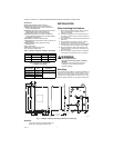
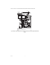
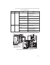
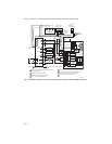
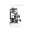
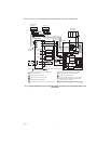
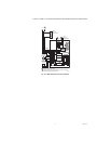
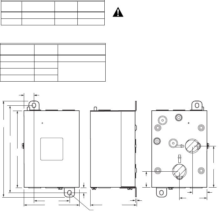
Mounting
The L7224A,C and L7248A,C,L models are available in a
well-mount, horizontal position, vertical position, or flush
mounted remote from the well versions. Dimensions for
the variety of mounting options are shown in Fig. 1. Note
that each identity will have only a single mounting option.
Fig. 1. L7224A,C; L7248A,C,L mounting dimensions in inches (mm).
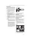
IMPORTANT
Immersion well must fit sensing element and
sensor must rest against bottom of well.
Part
Number
Spud Size
in. (mm)
Insertion
in. (mm)
Insulation
in. (mm)
123869A 1/2 (12.7) NPT 3 (76.2) 1-1/2 (38.1)
123870A 3/4 (19.05) NPT 3 (76.2) 1-1/2 (38.1)
Part Number
Length in.
(mm) Application
50001464-001 12 (304.8) Well-mounted controls
50001464-003 24 (609.6) Flush-mounted controls
50001464-004 36 (914.4)
50001464-005 48 (1219.2)
M22147B
3/4
(75)
5-11/16
(145)
3/8
(10)
2-5/8 (67)
7-1/8
(181)
6-1/2
(166)
3-13/32 (86)
2x 1/4 (7) x 3/8 (9)
1/16 (2)
1-3/16
(30)
3-1/32
(77)
2-1/16 (53)
1-1/8 (29)
4-1/4 (109)