


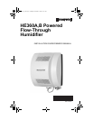
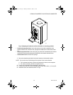
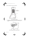
HE360A,B POWERED FLOW-THROUGH HUMIDIFIER
69-1176—04 4
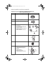
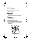
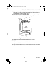
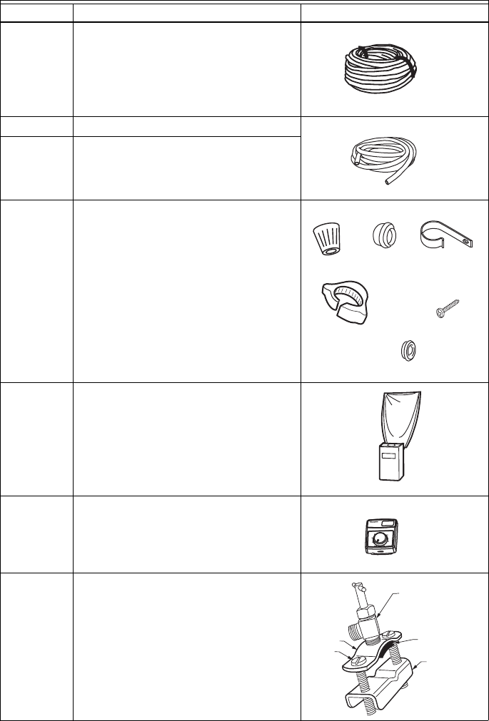
Installation Accessories (Available in Installation Kit 32005847-00)
Table 1. Required Accessories
Quantity Accessory Illustration
20 ft (6.2m) 18 gauge, two-strand thermostat wire
20 ft (6.2m) 1/4 in. (6.35 mm) OD feed water tubing
10 ft (3.1m) 1/2 in (12.7 mm) ID drain tubing
1 bag Connecting and mounting hardware:
Wire nuts (4)
No. 8 sheet metal screws (18)
Drain tube clamp
Feed tube mounting clamps (6)
Brass inserts (2)
Plastic compression rings (2)
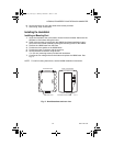
1 Sail switch
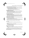
1 H8908 Humidistat
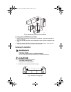
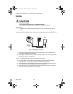
1 bag Saddle Valve Assembly:
Saddle valve and top clamp (1)
Threaded bottom clamp (1)
Bolts (2)
Rubber gasket (1)
Eyelet (1) not shown
Plastic bushing (1) not shown
THERMOSTAT WIRE
M31006
M31007
PLASTIC TUBING
M31015
#8 SHEET
METAL
SCREW
M31009
WIRENUT
M31014
DRAIN TUBE CLAMP
M31011
BRASS INSERT
M31012
PLASTIC RING
M31020
CLAMP
M31008
SAIL
SWITCH
Humidity Control
Régulateur d'humidité
-20 ¡
F
-
10 ¡F
0 ¡F
+10 ¡
F
+20 ¡F
Ov
er 20 ¡F
15%
20%
25%
30%
35%
40%
H
UMIDITY
SETTING
OUTDOOR
TEM
PERAT
U
RE
-30 ¡C
-25 ¡C
-20 ¡
C
-
10
¡
C
-5 ¡
C
Over 0 ¡
C
H8909 HUMIDISTAT
M31010
M31000
SADDLE VALVE
ASSEMBLY
SADDLE VALVE
BOLTS
BOTTOM
CLAMP
RUBBER
GASKET
TOP CLAMP
69-1176_A.fm Page 4 Monday, December 7, 2009 9:11 AM