HE120 BY-PASS DRUM HUMIDIFIER
69-1860EF—01 18
4. Plug the hole with nonflammable insulation to prevent
drafts from affecting the control.
5. Unscrew the Back Cover of Humidistat and remove.
See Fig. 39.
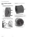
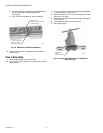
6. Unscrew the two Base Plate screws and remove the
Control Assembly. See Fig. 44.
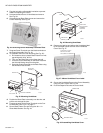
Fig. 44. Removing Control Assembly from Base Plate.
7. Snap two Screw Terminals over the blade terminals on
the Control Assembly. See Fig. 40.
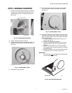
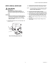
8. To assemble control for wall mounting (See Fig. 45):
a. Drill clearance hole in plastic Base Plate for low volt-
age wiring with 3/8 in. drill bit.
b. Turn over the Base Plate so text faces the wall.
c. Place the Control Assembly on the Base Plate with
the dial shaft facing away from the plate.
d. Screw the Control Assembly to the Base Plate using
the two Base Plate screws.
Fig. 45. Mounting Humidistat.
9. Position the Base Plate horizontally over the wire and
pull the wire through the hole.
10. Connect the wires to the Screw Terminals on the Con-
trol Assembly. See Fig. 41 on page 17.
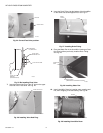
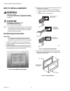
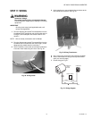
11. Secure Base Plate to the wall using four #6 x 1 in.
Sheet Metal Screws. See Fig. 46.
Fig. 46. Mounting Humidistat.
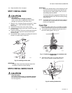
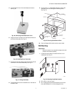
12. Remove the backing and adhere the Humidistat Label
to the recessed area of the front of the Humidistat
Cover. See Fig. 47.
Fig. 47. Adhere Humidistat Cover Label.
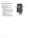
13. Secure the Humidistat Cover to the Control Assembly
using one 3/8 in. screw. See Fig. 48
14. Push the Setpoint Dial onto the control shaft.
Fig. 48. Assembling Humidistat Cover.
BASE PLATE SCREWS
M13634
M13612
BASE PLATE
CONTROL ASSEMBLY
DRILL 3/8 IN.
CLEARANCE
HOLE IN PLASTIC
BASE PLATE
SCREWS (2)
DIAL SHAFT
M13635
BASE PLATE
WITH CONTROL
ASSEMBLY
MOUNTED
SHEET METAL
SCREWS (4)
WALL
ALIGN HOLE IN COVER
WITH HOLE IN LABEL
FOR CORRECT PLACEMENT
M13636
60
10
M13614
BASEPLATE
COVER
SETPOINT DIAL
3/8 IN.
SCREW


