


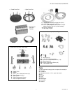

HE120 BY-PASS DRUM HUMIDIFIER
11 69-1860EF—01
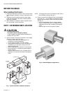
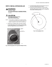
STEP 6: ASSEMBLE HUMIDIFIER
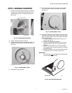
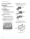
1. Position the Bearing Bracket inside the Humidifier
Housing to the side where the Bypass Duct is con-
nected. Make sure the “U” shape is pointing up.
See Fig 20.
Fig. 20. Installing Bearing Bracket.
2. Snap the Bearing Bracket into place.
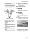
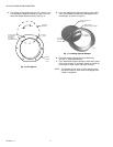
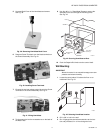
3. Position the Motor Plate on the opposite side of the
Humidifier Housing with the wires at the bottom.
See Fig 21.
Fig. 21. Installing Motor Plate.
4. Snap Motor Plate into place.
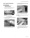
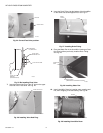
5. Place motor lead wires through bottom hole of Motor
Cover and snap into place on outside of Humidifier.
See Fig. 22.
Fig. 22. Installing Motor Cover.
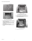
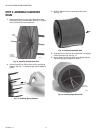
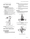
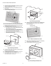
6. Install the Float Valve to the Humidifier Housing on the
same side as the Motor Plate. See Fig. 24. (If the Float
Valve is already installed on the same side as the Motor
Plate, skip this step.)
a. Unscrew Float Valve Retaining Nut using a 1/2 in.
wrench. See Fig. 23.
b. Remove Float Valve from housing.
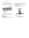
c. Place Float Valve Stem through “D” hole on same
side as the motor. See Fig. 24. (Float must be at
bottom.)
d. Place Float Valve Washer over Float Valve Stem
with recessed side of washer against the Humidifier
wall. See Fig. 25.
e. Secure Float Valve using Float Valve Retaining Nut
and tighten with 1/2 in. wrench. See Fig. 23.
IMPORTANT
The Float Valve must
be installed on the same side
of the Humidifier as the motor.
Fig. 23. Float Valve Retaining Nut.
SNAP TABS
INTO PLACE
“U” SHAPE FACES UP
M13624
M13625
MOTOR WIRES AT BOTTOM
M13610
VALVE SEAT
RETAINING NUT